3-Phase Motor Starter with Overload Protection: Sizing Guide
A starter is five tested parts, not a big contactor. Worked sizing for a 15 kW pump and a 7.5 kW fan, plus the five mistakes that survive commissioning.
Read More
Every auxiliary contact block carries two ratings that have nothing to do with its 10 A thermal current: an AC-15 rating at one voltage and a DC-13 rating at a much lower current on the same hardware. Read the wrong one — or assume “10 A means 10 A” — and a contact that has switched a coil happily for years will weld the first time it drops a DC load, or read “closed” into a PLC input that never sees a signal. This page explains both categories, shows the rating collapse voltage by voltage, and gives the selection rules for relays, PLC inputs and dry circuits.
Auxiliary (control-circuit) contact ratings are defined in IEC 60947-5-1, not the 60947-4-1 main-contact standard. The utilization categories that matter for control panels:
| Category | Load type | Typical duty |
|---|---|---|
| AC-14 | Control of small AC electromagnets ≤ 72 VA | Small contactor coils, solenoid valves |
| AC-15 | Control of AC electromagnets > 72 VA | Contactor coils 9 A and up, brake coils |
| DC-12 | Resistive DC, diode-clamped loads | LED panels, electronics |
| DC-13 | DC electromagnets | DC contactor coils, DC brake magnets, interposing relays |
| DC-14 | DC electromagnets with economy resistors | Larger DC brake magnets |
The 72 VA boundary splits AC-14 from AC-15 — it is a surrogate for how hard the coil’s inductance punishes the contact on break. In practice, “what contactor coil can this aux contact switch” is the AC-15 row, and “what DC coil or PLC load” is the DC-13 row.
Catalogue data for a typical 10 A thermally rated aux contact block (IEC 60947-5-1, values in line with published ABB CA5-type data) shows how fast the DC column collapses:
| Voltage | AC-15 Ie | DC-13 Ie (with rated power) |
|---|---|---|
| 24 V | 6 A | 6 A / 144 W |
| 48 V | — | 2.8 A / 134 W |
| 72 V | — | 1.0 A / 72 W |
| 110–127 V | 6 A | 1.1 A / 121 W |
| 125 V | — | 0.55 A / 69 W |
| 220–250 V | 4 A | 0.3 A / 75 W |
| 380–440 V | 3 A | — |
| 500–690 V | 2 A | — |
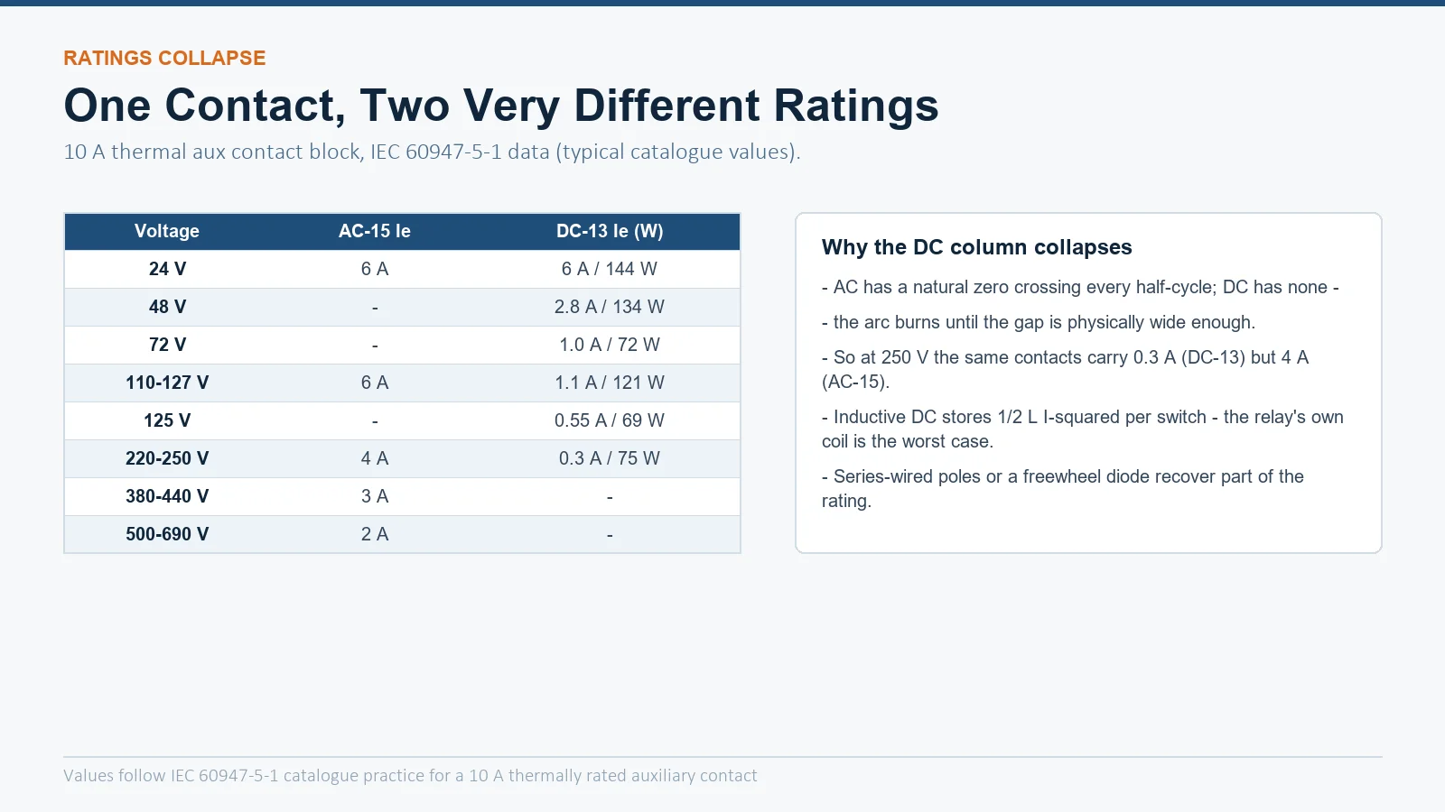
At 250 V the same contacts carry 4 A on AC but only 0.3 A on DC — a 13× collapse. The reason is physics, not conservatism: AC gives the contact a free arc extinction at every zero crossing, twice per cycle. DC has none, so the arc burns until the gap is physically wide enough to force the current down, and the inductive load keeps feeding it from its stored ½LI² energy — worst of all when the “load” is the relay’s own coil, which is exactly what a DC-13 duty usually is.
The test duties behind the two columns differ in shape:
| Category | Making | Breaking |
|---|---|---|
| AC-15 | 10 × Ie at cos φ 0.7 | Ie at cos φ 0.4 |
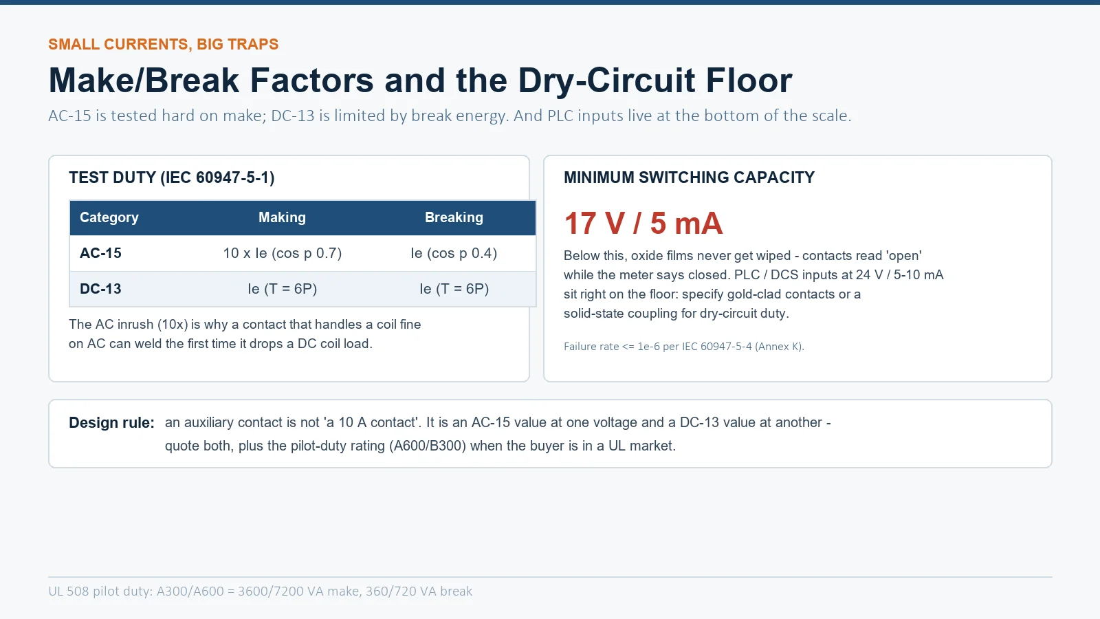
| DC-13 | Ie at time constant T = 6P | Ie at time constant T = 6P |
AC coil loads demand an inrush magnetizing current far above sealed current — hence the 10× making test, which is why an aux contact that survives AC coil duty can still fail on a DC switch: DC break duty is continuous arcing rather than a sharp inrush. Note that DC-13 is defined by a time constant proportional to power (T = 6P): bigger DC loads come with proportionally longer arc durations. This is the same zero-crossing physics behind main-contact DC ratings in our DC arc extinction guide.
There is a bottom to the scale too. Contact faces grow oxide films, and below a threshold voltage/current the contact never wipes the film away — the circuit reads “open” while the mechanism is closed. Standard silver contacts quote a minimum switching capacity around 17 V / 5 mA (failure rate ≤ 10⁻⁶ per IEC 60947-5-4 Annex K).
That matters because modern PLC and DCS inputs draw 5–10 mA at 24 V — right on the floor. Consequences:
AC ratings are quoted in apparent power (VA), DC ratings in real power (W) — they are not interchangeable in either direction. A coil “rated 24 V / 10 VA” draws its inrush in VA, not W; a DC brake magnet’s rating is its real heating. When the buyer sits in a UL market, the same contact appears a third way: pilot duty classes per UL 508, typically A600 (7200 VA make / 720 VA break) or A300 / B300 for smaller contacts. Quote all three languages on an export RFQ: AC-15 value at the control voltage, DC-13 value if DC coils are in the scheme, and the pilot-duty class.
For the switching hardware itself, our CJX2-F225 3-pole contactor accepts F-series add-on contact blocks with published AC-15/DC-13 ratings — the frames and accessories are listed in the AC contactor category.
Translate the categories into the loads a panel actually contains:
| Load | Category | Check |
|---|---|---|
| Coil of a 9–32 A contactor (24–230 VAC) | AC-14 | Sealed VA is small; the 10× inrush is the AC-14 test — standard aux contacts handle it |
| Coil of an 80–400 A contactor | AC-15 | Sealed draw can exceed 72 VA — verify the AC-15 Ie at your control voltage covers it |
| DC brake magnet or DC contactor coil | DC-13 | Use the W column at your DC voltage; add freewheel diode above a few tens of watts |
| PLC/DCS input (24 VDC, 5–10 mA) | Dry circuit | At the 17 V/5 mA floor — gold contacts or solid-state feedback |
| Pilot light, LED stack | DC-12 / AC-12 | Resistive; almost any contact qualifies |
Two boundary cases deserve a second look. A contactor coil rated 220–240 V on a large frame (say a 115 A or 225 A body) can draw 20–30 VA sealed and several hundred VA inrush — comfortably AC-15 territory, and the reason thin “contactor relay” contacts fail when someone reuses them for a big coil. And a DC control circuit at 220 V for a DC brake is exactly where the 0.3 A DC-13 ceiling bites: a brake magnet pulling 1 A will weld the contact on the first drop. The correct fix is poles in series plus a suppressor across the coil, as quantified in our surge suppressor guide.
Same contact, different load size. AC-14 covers control of AC electromagnets up to 72 VA; AC-15 covers above 72 VA. The 72 VA boundary reflects the higher inductive stress of larger coils on break.
DC has no zero crossing, so the contact must stretch and cool the arc on its own while an inductive load keeps feeding it. At 250 V the same physical contact carries 4 A on AC-15 but only about 0.3 A on DC-13.
Yes, within each column’s limits — they are independent ratings of the same contact. The classic mistake is protecting the DC leg with nothing: add a freewheel diode or RC across inductive DC loads and keep the current in the DC-13 band.