AC Contactor Market: Standards, Segments and Sourcing Regions
A structural map of the AC contactor market: the IEC, UL and NEMA standards worlds, four demand segments, and what each sourcing region is actually good at.
Read More
Choosing a thermal overload relay looks like one decision: find the relay whose dial covers your motor current, bolt it under the contactor, move on. In practice three independent choices decide whether that relay protects the motor or becomes a nuisance. A correctly ranged relay will still nuisance-trip a 12-second conveyor start if the trip class is wrong. A relay with the perfect class is still a hazard on a jammed screw conveyor if the reset selector is left in automatic.
This guide follows the order a panel builder actually works in: nameplate data, setting range, heating type, trip class, reset mode, then mounting and environment.
A thermal overload relay models the heat building up in a motor winding. Current heats a bimetallic strip, the strip bends, and a snap mechanism opens the normally closed 95-96 contact. That contact sits in series with the contactor coil, so the contactor drops out and the motor stops. The physics is covered in our guide to how a thermal overload relay works.
For selection, the relay has to mirror one motor on one machine along three axes:
Trip class and ambient compensation sit on top as modifiers. Work through the steps in order.
The nameplate full-load current (FLA, also printed as FLC or rated current) is the only authoritative anchor. Motor power in kW is a cross-check at best: two 11 kW motors from different efficiency classes draw different full-load amps at the same voltage. Record rated current, voltage, frequency, service factor, and duty type before opening a catalogue, then check two things that catch people out.
Under NEC Article 430.32, a motor with a nameplate service factor of 1.15 or higher may be set to no more than 125% of FLA; a service factor 1.0 motor, or one with temperature rise above 40 °C, is limited to 115%. IEC practice is tighter: set at 1.0 times FLA for continuous duty, up to about 1.05 times for light or intermittent duty. A 28 A motor with a 1.15 service factor has a legal ceiling of 35 A, but 28 A is still the value you start from.
In a star-delta starter the relay usually sits in the phase path, not the line path, so it carries only phase current. Set it to FLA divided by 1.73, following the starter’s own wiring diagram. Setting it to full line FLA leaves the motor effectively unprotected during run.
Thermal relay setting ranges are narrow — typically a 1.5 to 1 window, such as 7.5–11 A or 17–25 A. The FLA must fall inside that window, ideally in the middle third.
Why the middle? A set point near the bottom leaves no margin below, so a cold morning or a voltage sag causes nuisance trips. A set point near the top leaves no margin above, so a genuine overload sits too close to the threshold. IEC 60947-4-1 sets the envelope: the relay must not trip at 1.05 times the set current for two hours, and must trip within two hours at 1.2 times.
| Motor FLA | Relay range | Where FLA lands | Verdict |
|---|---|---|---|
| 4.0 A | 3.0 – 5.0 A | Middle | Correct choice |
| 4.0 A | 4.0 – 6.0 A | Bottom of dial | No adjustment below FLA — reject |
| 18 A | 14 – 22 A | Middle | Correct choice |
| 18 A | 12 – 18 A | Top of dial | Setting sits at the range limit — reject |
| 30 A | 50 – 80 A | Not reachable | Dial cannot reach the set point — no protection |
Heating type describes how motor current reaches the bimetallic strip, and current magnitude picks the type for you.
Indirect heating passes current through a heater winding coiled around an insulated bimetal, so the heater can be selected independently of the strip. It covers roughly 0.1–20 A but responds slowly and withstands about 16 times the adjusted current. Direct heating uses the bimetal itself as the heating element, giving fast response and up to 30 times short-circuit withstand, but below about 20 A the I²R dissipation is too small for reliable deflection — hence its 20–70 A band. Composite heating sits between the two, with heater resistance tuned by series or parallel connection; it is the most common general-purpose arrangement. Current-transformer heating heats the bimetal from a CT secondary, keeping the element compact with the highest withstand, around 50 times.

| Heating type | Typical current band | How the bimetal is heated | Short-circuit withstand | Typical application |
|---|---|---|---|---|
| Indirect | ≈ 0.1 – 20 A | Separate winding around the bimetal | ≈ 16 × Iset | Small motors, control panels |
| Direct | ≈ 20 – 70 A | Motor current flows through the bimetal | ≈ 30 × Iset | Mid-size motors, compact starters |
| Composite | ≈ 10 – 60 A | Winding and bimetal share the current path | Between direct and indirect | General-purpose motor starters |
| Current transformer | > 60 A | Secondary winding of a CT heats the bimetal | ≈ 50 × Iset | Large motors, MCC starters |
Trip class declares how long the relay tolerates starting current, measured at 7.2 times the set current from cold. It exists because a motor draws five to eight times full-load current while accelerating, and the relay must ignore that inrush without ignoring a real overload. Measure the actual start time where you can; otherwise use the load type as a proxy and verify on commissioning.
| Measured start time | Choose | Trip window at 7.2 × Iset | Typical loads |
|---|---|---|---|
| Under 5 s | Class 10A | 2 – 10 s | Centrifugal pumps, light compressors, small fans |
| 5 – 10 s | Class 10 | 4 – 10 s | Standard induction motors, direct-on-line |
| 10 – 20 s | Class 20 | 6 – 20 s | Loaded conveyors, screw compressors, mixers |
| 20 – 30 s | Class 30 | 9 – 30 s | Large fans, crushers, centrifuges, mills |
An unmarked relay is generally assumed to be Class 20. If a relay nuisance-trips during a normal start at the correct current setting, the class is wrong, not the dial. Raising the dial to stop a start-time trip is the most common way motors end up unprotected.
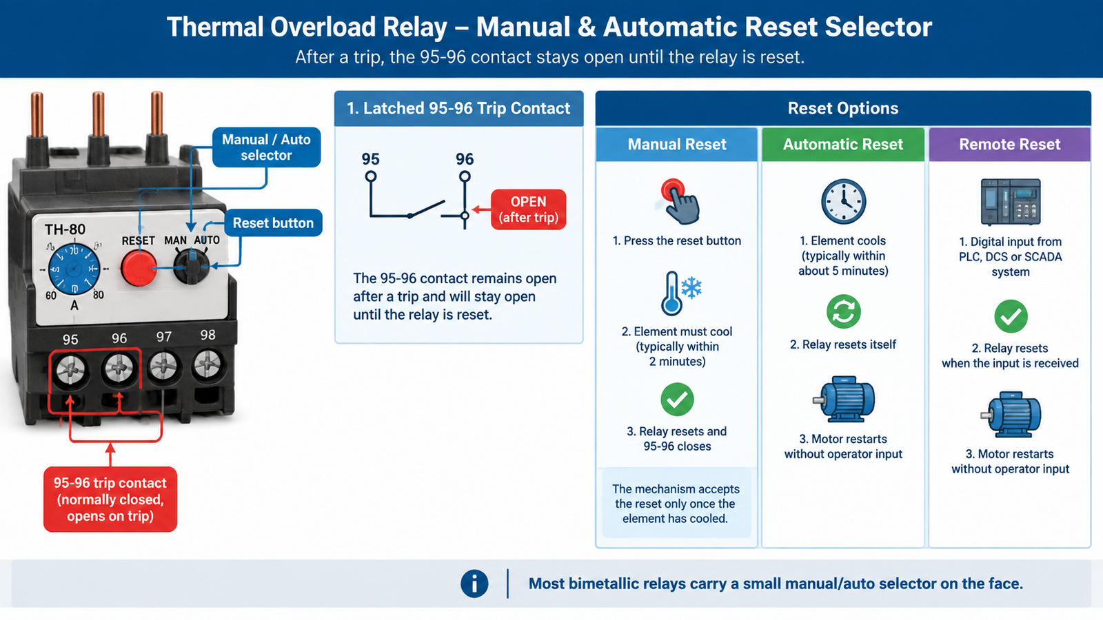
After a trip, the 95-96 contact stays open until the relay is reset. How that reset happens is a safety decision, not a convenience one.
An operator presses the reset button on the relay face, and the mechanism only accepts the reset once the element has cooled — typically within two minutes. Because the motor cannot restart until a person intervenes, the trip cause gets investigated. This is the correct default for attended installations, for machines where an unexpected restart could injure someone, and wherever lockout/tagout applies.
The relay resets itself once the element cools, typically within about five minutes, and the motor restarts with no operator input. This suits only unattended, remotely located equipment where a restart after a transient event is operationally required — remote pump stations, rooftop HVAC units, booster sets. The risk is a persistent fault driving repeated trip-restart cycles that accelerate winding damage.
Common on electronic relays, remote reset takes a digital input from a PLC, DCS, or SCADA system. It avoids panel access in large or hazardous installations while still requiring an intentional command rather than an automatic restart, which makes it the standard choice for intelligent MCC lineups.
| Reset mode | Reset timing | Use when | Avoid when |
|---|---|---|---|
| Manual | Typically ≤ 2 min after cooling | Attended plant, safety-critical machines, lockout/tagout applies | Site is genuinely unmanned |
| Automatic | Typically ≤ 5 min after cooling | Remote pump stations, rooftop HVAC, booster sets | Jamming or mechanical faults are plausible |
| Remote (electronic) | On command | PLC or SCADA controlled starters, intelligent MCC | No supervisory system exists |
Most bimetallic relays carry a small manual/auto selector on the face. Confirm its position at commissioning and record it — a selector in the wrong position stays invisible until the day it matters.
A contactor-mounted relay snaps onto the load-side terminals of the matching contactor, producing a compact starter with no intermediate wiring. That mechanical match is brand-specific: a relay designed for one manufacturer’s contactor family will not dock onto another’s, and mixing brands voids the published coordination data and the listed assembly status.
Specify the relay from the same family as the contactor whenever it is plug-in mounted, and move to a stand-alone chassis-mount relay above roughly 100 A, for retrofits, and for busbar-fed MCC starters. If you are still deciding on the switching device, our guide to how to size and select an AC contactor covers the contactor side of the pairing, and the LC1-D series contactors show the frame sizes a relay may need to fit.
The 95-96 contact goes in series with the contactor coil; the 97-98 contact is free for alarm or PLC indication. Check that the auxiliary contact rating covers your control circuit voltage.
Bimetallic relays are temperature-compensated, but only within limits. IEC-compliant compensation typically spans about −5 °C to +40 °C; wider-range relays reach −25 °C to +60 °C. Outside that band the trip point drifts.
Overload protection also has to coordinate with the short-circuit device: the relay handles sustained overloads, the fuse or breaker clears faults. Our comparison of contactor and circuit breaker duties explains why the two roles cannot be merged, and contactor, relay, and short-circuit device should be treated as one coordinated set.
The table below compresses the sequence into starting points. Confirm each against actual nameplate data before ordering.
| Application | Heating type | Trip class | Reset mode | Notes |
|---|---|---|---|---|
| Small pump, direct-on-line | Indirect | Class 10A | Manual | Fast start, low inertia |
| HVAC fan, contactor-mounted | Composite | Class 10 | Manual | Verify the brand match to the contactor |
| Loaded conveyor | Composite | Class 20 | Manual | Measure the real start time first |
| Screw compressor, 30–75 A | Direct | Class 20 | Manual | Frequent starts need headroom in the range |
| Large crusher or mill | Current transformer | Class 30 | Manual | Stand-alone mounting, busbar fed |
| Remote booster set | Composite | Class 10 | Automatic | Only where restart is operationally required |
Selection comes down to working in the right order. Take the nameplate FLA, apply the service factor limit, and find a range that puts the set point mid-dial. Let current magnitude pick the heating type — indirect below 20 A, direct in the mid range, current transformer above 60 A. Match the trip class to the measured start time, then treat the reset mode as a safety decision and default to manual. Finish by confirming the contactor match and correcting for ambient temperature, enclosure, and orientation.
When relay, contactor, and short-circuit device are selected as one coordinated set, the starter stops being a collection of parts and starts behaving like a protection system. Our guide to choosing a contactor for a motor starter covers the switching and overload pairing in more detail, and the CJX2-D (LC1-D) series contactors show the frame sizes that accept direct-mounted overload relays.
Set it to the motor’s nameplate full-load current for the actual supply voltage and connection, choosing a range that brackets that value with the set point near mid-dial. NEC Article 430.32 permits up to 125% of FLA for service factor 1.15 motors and 115% for service factor 1.0 motors, but nameplate FLA remains the starting reference.
Current magnitude decides it: indirect heating covers roughly 0.1–20 A, direct heating 20–70 A, and current-transformer heating above about 60 A. Composite heating covers the middle band. Direct and current-transformer types also offer higher short-circuit withstand.
Manual reset requires an operator to press the button, and the relay accepts it only after the element cools — typically within two minutes. Automatic reset clears itself once the element cools, typically within about five minutes, and the motor restarts without intervention. Manual is the correct default for attended installations.
No. Automatic reset lets the motor restart without anyone checking why it stopped. Where a jam or seized bearing is plausible, repeated trip-restart cycles can damage the winding, and lockout/tagout procedures assume the motor stays stopped.
Usually because the trip class is too low for the actual acceleration time. A motor taking 12 seconds to reach speed will nuisance-trip a Class 10 relay even at the correct setting; the fix is Class 20, not a higher dial. A set point near the bottom of the range can also cause start-time trips.
Not on a plug-in, contactor-mounted assembly. Each manufacturer’s relay is mechanically matched to its own contactor family, and the published coordination data applies only to the matched pair. Stand-alone chassis-mount relays can be wired separately, but you lose that coordination data.