How to Reset an AC Contactor: Step-by-Step Guide
An AC contactor has no reset button. Learn which device actually tripped, how to reset the overload relay safely, the cool-down rule, and when to replace instead.
Read More
A contactor rarely fails without warning. It erodes, it hums, it runs a little hotter, and then one shift it welds shut or drops out under load. Effective contactor maintenance is simply the discipline of catching those three slow signals — contact erosion, coil degradation, and loose terminations — before they cascade into a stopped line.
If you want a defensible baseline: a monthly visual and audible check, a quarterly thermographic scan on motor starters, and annual electrical testing of contacts and coils. But the calendar is only a starting point. The interval that actually protects your equipment is driven by switching operations, duty category, and environment — not by the month on the wall. This guide gives you the inspection points, the measurable acceptance criteria, and a method for setting intervals from your real duty cycle.
Two wear mechanisms run in parallel inside every contactor, and they fail at completely different rates.
The practical consequence: a contactor’s useful life is set almost entirely by how many times it switches under load, and at what current. A unit switching an AC-1 lighting circuit twice a day will outlast the building. The same frame on an AC-4 jogging duty cycling hundreds of times per hour can be at end of life in two years. Environment then multiplies the effect — sustained ambient above the reference temperature accelerates insulation ageing and shortens electrical life appreciably, and dust or corrosive vapour attacks both the pole faces and the terminations.
That is why a maintenance programme built purely on a fixed annual shutdown misses the failures that matter. The high-cycle contactor is already worn out while the low-cycle unit next to it is barely broken in.
Contactors are fed from live busbars, and the coil circuit is often supplied from a control transformer that stays energised from a different source. Isolation must cover both.
Live testing is only justified for the specific measurements that require it: thermographic scanning under load, and pickup and drop-out voltage verification. Both should be done by qualified personnel under a documented live-work procedure.
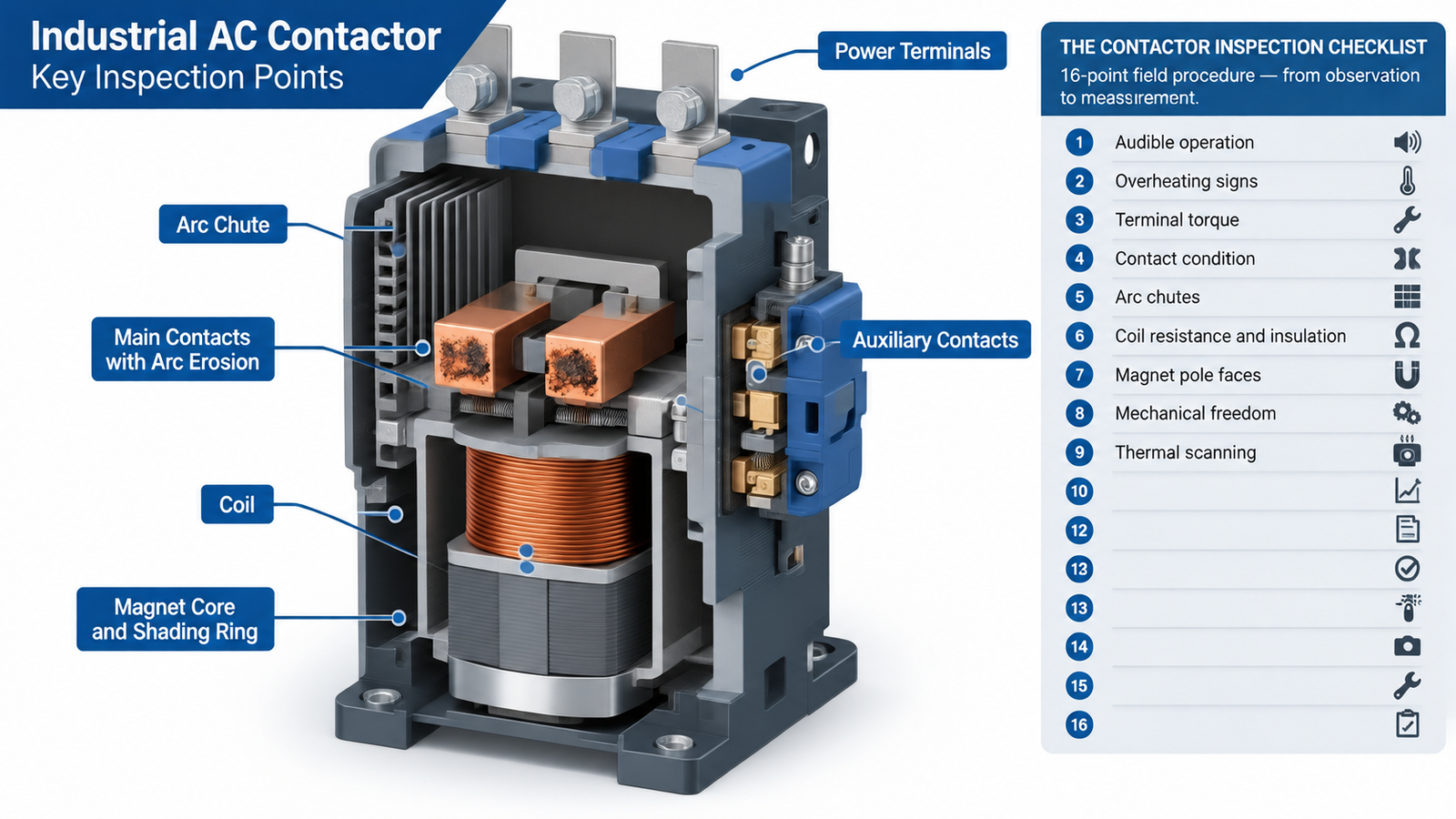
This is the core field procedure. Work through it in order — the sequence moves from observation to measurement, so you gather evidence before disturbing anything.
| # | What to check | How to check it | Acceptance criterion | Action if it fails |
|---|---|---|---|---|
| 1 | Audible operation | Listen during a normal start and stop | Single firm closure, no sustained hum | Investigate pole faces and shading ring before anything else |
| 2 | Enclosure and ventilation | Visual, with the panel closed | No dust build-up, filters clear, seals intact | Clean and replace filter media; re-check ambient temperature |
| 3 | Signs of overheating | Visual on terminals, insulation, plastic parts | No discolouration, no warping, no burnt odour | Measure contact resistance and terminal torque; investigate load current |
| 4 | Terminal tightness | Torque wrench on every power and control terminal | Within the OEM torque table for the frame size | Re-torque to specification; replace any heat-damaged conductor |
| 5 | Main contact condition | Open the arc chamber and inspect | Even silver-grey surface, no deep craters, no material transfer | Measure contact gap (see next section) before deciding |
| 6 | Contact gap / wear | Caliper or feeler gauge against OEM new value | Within OEM limit; commonly reject near 50% material loss | Replace contacts or the contactor |
| 7 | Three-pole simultaneity | Inspect closure marks on all three poles | All poles close together, even wear pattern | Check for single-phasing or load imbalance in the circuit |
| 8 | Arc chutes | Visual, then dry brush or vacuum | No carbon bridging, no cracked or displaced plates | Clean; replace if plates are damaged or bridging cannot be removed |
| 9 | Coil resistance | Ohmmeter across coil terminals, power off | Within about ±10% of nameplate or OEM value | Replace the coil |
| 10 | Coil insulation | Insulation tester, coil to earth | Typically 10 MΩ or better on a 400 V circuit | Replace the coil immediately |
| 11 | Coil temperature | Contact thermometer or thermal camera while energised | Stable, no discolouration, no varnish smell | Verify control voltage and control transformer regulation |
| 12 | Magnet pole faces and air gap | Visual with armature manually closed | Clean faces, no rust, gap within OEM value when closed | Clean the air gap; replace a broken shading ring |
| 13 | Mechanical freedom | Press the armature closed by hand or test button | Smooth travel, crisp return, no binding | Clean pivots; replace if return is sluggish (spring fatigue) |
| 14 | Auxiliary contacts | Inspect and exercise; check alignment | Free movement, no burning, correct travel | Replace the auxiliary block |
| 15 | Overload relay setting | Compare dial setting to motor full-load current | Matches the motor nameplate FLC and duty class | Reset to the correct value and re-test trip function |
| 16 | Thermal image under load | Scan terminations and poles while running | No connection more than about 10 °C above its own baseline | Re-torque, clean, or replace the connection; re-scan |
Almost every checklist says “inspect the contacts” and stops there. Inspection by eye is unreliable, because a contact that looks grey and pitted may still be well within limits, while one that looks acceptable may already be at the rejection point. Measure instead of guessing.
The field-usable measurement is contact gap: the distance the moving contact travels, or the residual gap in the closed position, compared with the OEM new value. Record the number, not an adjective. A gap that has grown by roughly half the available contact material is the common practical rejection point, and the OEM data sheet overrides any general rule.
Two rules matter more than the measurement itself:
The coil is the cheapest component in the contactor and the cause of a disproportionate share of failures. Four measurements cover it.
| Measurement | Method | Expected result | What a bad reading means |
|---|---|---|---|
| Coil resistance | Ohmmeter across coil terminals, isolated | Within about ±10% of the OEM value, corrected for ambient temperature | Open circuit = burnt out; high reading = partial winding damage; low reading = shorted turns |
| Insulation resistance | Insulation tester, coil winding to earth | Typically 10 MΩ or better on a 400 V circuit | Low reading indicates moisture ingress or degraded winding insulation — replace, do not dry out and reuse |
| Pick-up voltage | Raise control voltage slowly from zero | Firm pick-up within the IEC 60947-4-1 operating band of 0.85 to 1.1 × Uc | Failure to pick up in band points to a weak coil, excessive air gap, or mechanical binding |
| Drop-out voltage | Lower control voltage slowly until the contactor releases | Releases within the standard drop-out band of 0.2 to 0.75 × Uc | Releasing too early causes nuisance drop-out on voltage dips; releasing too late indicates a stuck armature |
Coil temperature deserves its own note. A coil that runs hot enough to discolour its former or smell of varnish is being over-driven, and the usual cause is not the coil. Check the control voltage against the coil rating and check the regulation of the control transformer under load. If the coil is not receiving the voltage it was designed for, you will keep replacing coils. The dual voltage marking on modern contactor coils is a frequent source of exactly this mistake.
Continuous humming is the most misdiagnosed symptom in contactor maintenance, and it is almost never the coil. Three causes account for the overwhelming majority of cases:
One warning: do not lubricate pole faces or contacts. Lubricant attracts dust, carbonises, and creates exactly the contamination you are trying to remove. Lubrication belongs on pivots and bearings, sparingly, and never where it can migrate onto electrical contact surfaces.
Loose terminations are among the most common root causes of contactor problems, and they are also the easiest to prevent. Thermal expansion and vibration steadily reduce terminal tightness, which raises resistance, which raises temperature, which accelerates further loosening. Torque every power and control terminal to the manufacturer’s table for that frame size — control terminals on small frames commonly fall in the 1.2 to 2.5 N·m range, but never substitute a general figure for the OEM specification.
Thermography is the most efficient way to find connections that are already degrading. Scan under normal load and compare each termination against its own historical baseline rather than against a fixed absolute temperature, because load and ambient change between visits. A connection running roughly 10 °C above its own established baseline is the signal to intervene — re-torque it, clean it, and scan again to confirm the correction worked. Trending matters more than any single reading.
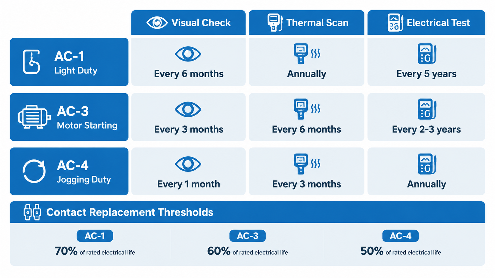
Rather than applying one interval to every contactor in the plant, tier the programme by how hard the device actually works. The table below is a workable framework; adjust it for environment and for the consequence of failure.
| Programme element | Light duty (AC-1, low operations per day) | Standard duty (AC-3, motor starting) | Heavy duty (AC-4, jogging and plugging) |
|---|---|---|---|
| Visual and audible check | Every 6 months | Quarterly | Monthly |
| Thermographic scan under load | Annually | Every 6 months | Quarterly |
| Contact and coil electrical testing | Every 5 years | Every 2 to 3 years | Annually |
| Contact replacement threshold | At about 70% of rated electrical life | At about 60% of rated electrical life | At about 50% of rated electrical life |
| Typical service life | 15 to 20 years | 8 to 12 years | 2 to 5 years |
Then apply three modifiers:
Thermography and scheduled electrical testing are complements, not substitutes. Thermal scanning catches resistive connections and overloaded poles between outages; insulation testing catches winding and insulation degradation that never shows up as heat. A mature programme runs both.
The value of an inspection is not the list of problems — it is the root cause behind each one. The same visible failure can have very different origins.
| Finding | Mechanism | Root cause to investigate |
|---|---|---|
| Welded contacts | Interrupting capacity exceeded; the arc held until the surfaces fused | Check short-circuit coordination. If the installation requires Type 2 coordination per IEC 60947-4-1, the contactor must remain suitable for further use after a short circuit; repeated welding under Type 2 requirements points to a coordination problem upstream, not a contactor problem |
| Asymmetric erosion between poles | One pole interrupting more than its share | Single-phasing during switching, a broken conductor on one phase, or unbalanced load |
| Symmetric but premature erosion | More current or more operations than the device was sized for | Duty cycle has drifted beyond the original selection; re-check the utilization category |
| Coil burnout | Sustained overvoltage, or being held partially picked up so inrush current never drops to the sealed value | Control transformer regulation and control voltage; ambient above the coil’s thermal class |
| Continuous hum | Air gap in the magnetic circuit | Contaminated pole faces or a broken shading ring — not the coil |
| Heavy carbon in the arc chute | Arc energy higher than the chute was designed to handle | Interruption duty above rating, or a chute that is already damaged or misaligned |
| Discoloured terminals | Resistance heating at the connection | Under-torqued terminal, corroded conductor, or undersized cable |
For symptom-led diagnosis when something is already misbehaving, the structured approach in this contactor troubleshooting walkthrough maps sounds and readings to causes, and the no-instrument field checks are useful for operators who need to flag a suspect device before a technician arrives.
Maintenance decisions go wrong in both directions: replacing serviceable devices wastes money, and repairing worn ones causes repeat failures. Use evidence, not instinct.
If the decision is trending toward replacement, the diagnostic question “is this device actually bad?” is worth answering properly first — the criteria for condemning a contactor are set out in how to tell whether an AC contactor is bad. And where the device has tripped rather than failed, follow the correct re-arm procedure in how to reset an AC contactor before condemning it — and confirm the overload relay setting and reset mode match the motor, since a mis-set relay produces symptoms that look like contactor failure.
Maintenance speed depends on what is already in the store. Stock by criticality rather than by convenience.
| Spare | 중요한 이유 | Priority |
|---|---|---|
| Coils, matched to control voltage and frame | Most common replaceable failure; small, cheap, high turnover | 높음 |
| Contact kits for the most-used frame sizes | Turns a replacement into a repair where it is economic | Medium |
| Auxiliary contact blocks | Restores control circuits without replacing the main device | 높음 |
| Complete contactors of each critical frame size | Fastest possible return to service on a critical process | High for critical duty only |
| Arc chute assemblies | Only economical on larger frames | Low to medium |
| Overload relays covering your motor range | Relay faults mimic contactor faults and cause repeat trips | Medium |
To identify which internal part you are looking at during an inspection, the component-by-component breakdown in inside an AC contactor is a useful reference to keep with the maintenance documentation.
A maintenance programme without records is a series of unrelated events. Trending is what converts individual readings into early warning, and it is the only way to justify a replacement before a failure.
Record at minimum: date and device tag; switching operation count if available; contact gap measurements per pole; coil resistance and insulation resistance; pick-up and drop-out voltage; thermographic readings per termination with load and ambient at the time; torque values applied; parts replaced; and the technician’s assessment of remaining life. The critical detail is that each measurement must be comparable to the last one, so note the conditions under which it was taken. A temperature reading with no load figure attached is useless six months later.
Contactor maintenance works when it is built around three ideas: measure rather than judge by eye, set intervals from switching operations rather than the calendar, and read every finding back to its root cause. A sixteen-point inspection that produces numbers — contact gaps, coil resistances, torques, thermal deltas — will outperform any checklist that produces only adjectives, and it will tell you when to replace a device before it takes a process down.
Start with the devices on your heaviest duty and your most critical processes. If you are specifying replacements as part of that programme, the AC contactor range covers frames from small control duty up to heavy industrial motor starting, including the LC1-E series rated up to 95 A for standard AC-3 motor duty. Match the frame to your measured duty cycle, and keep the coil and auxiliary spares that match it on the shelf.
It depends on duty, not on the calendar. A reasonable baseline is a visual and audible check every six months for light AC-1 duty, quarterly for AC-3 motor starting, and monthly for AC-4 jogging and plugging. Thermographic scanning follows a similar tiering — annually, every six months, and quarterly respectively — with full electrical testing of contacts and coils at five years, two to three years, and annually. Shorten every interval in hot, humid, dusty, or corrosive environments.
No. Silver-based contacts depend on their surface layer for low resistance, and abrasion removes it while leaving a rough surface that arcs more aggressively. Light discolouration and small pits are normal service conditions and should be left alone. Replace contacts that are deeply cratered, cracked, or showing material transfer. If you must handle eroded contact material, wear respiratory protection — silver cadmium oxide contacts contain cadmium and the dust is toxic.
Almost always because there is an air gap in the magnetic circuit, not because the coil is failing. The two common causes are contaminated or rusted pole faces that prevent full closure, and a broken or missing shading ring — the short-circuited copper ring on an AC magnet core that prevents chatter at twice line frequency. Clean the pole faces with a lint-free cloth and isopropyl alcohol first; if the hum persists and the shading ring is damaged, the contactor needs replacing. Never lubricate pole faces.
Coil resistance should sit within roughly 10% of the manufacturer’s stated value, corrected for ambient temperature. Insulation resistance from winding to earth should typically be 10 MΩ or better on a 400 V circuit. For main contacts, compare pole-to-pole readings against each other rather than against a fixed number: a pole reading significantly higher than its neighbours indicates localised erosion or a poor connection, and a spread between poles often points to single-phasing or load imbalance.
Replace when the failure is internal and mechanical — a damaged arc chute, a failed shading ring, a binding armature, weakened springs, or unreliable auxiliary contacts — because field maintenance cannot restore these. Also replace when contact wear exceeds the manufacturer’s limit, when the device has had repeated repairs in a short period, when it has exceeded expected service life for its duty tier, or when it is obsolete with no available spares. Coils and auxiliary blocks, by contrast, are normally worth replacing in place.
Yes, in several practical ways. Keep the enclosure clean and ventilated so ambient stays near the reference temperature, since sustained heat accelerates insulation ageing. Re-torque terminations on schedule to stop resistance heating. Correct the control voltage so the coil receives what it was designed for, rather than operating at the edge of its band. And where the duty has crept upward — more operations, more jogging, higher current — re-check that the frame is still correctly sized for the new load, because an undersized device will wear out regardless of how well it is maintained.