Rotary Encoder Knob with Push Button and Detents
Wilmall supplies Rotary Encoder Knob for B2B buyers, wholesalers and exporters, with factory price, OEM/ODM, custom, private label and white label service.
Read More
Every inquiry that mentions “absolute rotary encoder” eventually hits the same fork: absolute or incremental? The two technologies answer different questions about a shaft, cost different amounts, and fail in different ways — yet most comparison content online stops at “absolute remembers position, incremental does not”, which is not enough information to specify anything. This guide covers the three decisions that actually determine the choice — position retention, reference logic, and interface — plus the resolution, speed and protection levels that finish the specification.
One disclosure before the tables: our rotary encoder range is incremental encoder products, so this article is written from the position of a supplier that sells incremental daily and specifies absolute when the application demands it. That is also the honest way to read the decision path at the end.
| Decision | Choose absolute when | Choose incremental when | Why it matters |
|---|---|---|---|
| Position retention after power loss | Axis must be usable immediately after re-power, or re-homing is unsafe/expensive | Machine homes at every start anyway; power cycles are planned | Defines commissioning time and recovery behaviour |
| Reference / homing logic | No reference switch wanted — position is known from the code disc itself | Homing routine to a switch or mark is acceptable, even desirable for accuracy | Drives hardware cost and start-up sequence |
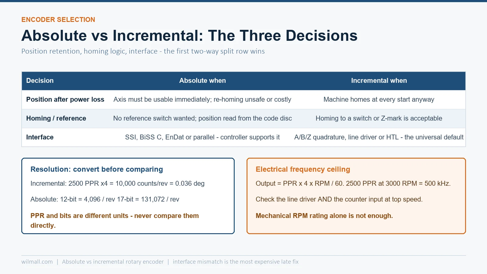
| Interface and distance | SSI, BiSS C, EnDat, or parallel — controller supports it natively | A/B/Z quadrature, line driver (RS-422), open collector — the universal default | Wrong interface means an extra converter or a controller swap |
If all three rows point the same way, the decision is done. When they split — say, re-homing is acceptable but the interface must be SSI — the split row wins, because interface mismatches are the most expensive to fix late.
 ” />
An incremental encoder outputs pulses as the shaft turns. The controller counts pulses from a known reference; the count is the position. Nothing in the encoder “knows” an absolute angle — the position exists only as the controller’s accumulated count. Power loss or a glitch erases it, and the machine must re-home to a reference switch or Z-index mark to recover. The technology’s strengths follow from this simplicity: few conductors, high resolution cheaply (a 2500 PPR disc is commodity hardware), and noise immunity through differential line signals.
An absolute encoder reads a physically coded pattern on the disc — single-turn absolute gives a unique code for every angle within one revolution; multi-turn absolute additionally counts revolutions through gearing or electronic memory. The position is read, not accumulated, so it survives power loss without batteries (for optical multi-turn) or with them (for electronic multi-turn). The costs are the coded disc, the serial interface electronics, and roughly a 2–5× price multiple over an incremental unit of the same mechanical size.
Incremental resolution is quoted in PPR (pulses per revolution): 100, 250, 500, 1024, 2500 are the standard steps. The controller multiplies by 4 with quadrature decoding, so a 2500 PPR encoder yields 10,000 counts per revolution. Absolute resolution is quoted in bits: 12-bit single-turn = 4,096 positions per revolution, 17-bit = 131,072. Comparing “2500 PPR” with “17-bit” directly is a category error — convert both to counts per revolution before deciding which is finer.
| Need | Incremental (quadrature counts) | Absolute (bits) | Reality check |
|---|---|---|---|
| Motor commutation / speed loop | 100–2500 PPR | — | Commutation needs U/V/W hall tracks, not just counts |
| Positioning to 0.1° | ≥ 3600 counts/rev → 1024 PPR (with ×4) | ≥ 12-bit | Either technology reaches this cheaply |
| Positioning to 0.01° | ≥ 36,000 counts/rev → 10,000 PPR class | ≥ 15-bit | Absolute gets more economical here |
| Linear positioning on a ball screw | Resolution ÷ pitch × gear ratio | Same, plus multi-turn if screw > 1 rev per stroke | Multi-turn range must exceed the stroke’s revolutions |
The reason absolute encoders exist is not elegance — it is what happens after power loss. Assess your re-homing reality with three questions:
If any answer is “no, expensive, or yes”, absolute encoding is justified regardless of the price multiple. If all three are benign, the incremental encoder’s simplicity is an advantage: fewer failure modes, a universal interface, and the cheapest replacement part in the cupboard. Our GOS38D incremental rotary encoder covers the standard 38 mm industrial footprint for exactly those applications.
Multi-turn absolute encoders come in two constructions. Optical/mechanical multi-turn uses a gear train inside the encoder — no battery, position survives any power interruption indefinitely, higher cost and a taller body. Electronic multi-turn uses a counter backed by a capacitor or battery — slimmer and cheaper, but the counting principle needs power maintenance: capacitors hold for days, batteries for years with a replacement schedule. Specify the construction deliberately; “multi-turn absolute” alone does not tell you which behaviour you bought.
| Interface | Technology | Max practical distance | Controller requirement | Notes |
|---|---|---|---|---|
| A/B/Z quadrature + line driver | Incremental | ~100 m (RS-422 differential) | High-speed counter input | The universal default; open-collector variants suit short runs |
| Push-pull / HTL | Incremental | ~50 m | 24 V counter input | Common on PLC high-speed inputs |
| SSI | Absolute | ~100 m | SSI master or dedicated input | Simplest absolute interface; clock-driven, no protocol stack |
| BiSS C | Absolute | ~100 m | BiSS master | Higher cycle rates, register access, parameter channel |
| EnDat 2.2 | Absolute | ~100 m | Drive with EnDat | Vendor ecosystem (Heidenhain); diagnostics and parameter storage |
| Analog (0–10 V / 4–20 mA) | Potentiometer-type / sensor | Short; noise-sensitive | Analog input | Not an encoder interface in the strict sense; included because it appears in inquiries |
The interface check that saves the most pain: confirm the master side before ordering the encoder. A PLC with only high-speed counter inputs cannot read SSI without an add-on module; a servo drive configured for EnDat will not accept BiSS C. Reverse cases exist too — adding an absolute encoder to a controller that only counts quadrature is the most common dead-end we see in specification reviews.
Mechanical speed ratings (RPM) get all the attention, but incremental encoders also have an electrical ceiling: output frequency = PPR × 4 × RPM ÷ 60. A 2500 PPR encoder at 3000 RPM produces 500 kHz — above the rating of some counter inputs and cable runs. Either reduce resolution or check that the line driver and the controller input both handle the frequency with margin. Absolute serial interfaces have their own cycle-time limits (SSI clock rates), which cap position update rate rather than speed itself.
| Environment | Minimum rating | Additional requirements |
|---|---|---|
| Clean indoor panel | IP50/IP54 | Standard shaft seal |
| Machining splashes, humid workshops | IP65 | Radial shaft seal, corrosion-resistant housing |
| Washdown, outdoor, dust-laden | IP67 | Laser-welded housing, wide temperature elastomers |
| Continuous immersion / high-pressure jets | IP68/IP69K | Special sealing systems; verify with the manufacturer, not the datasheet boilerplate |
Two mechanical details decide survival more than the IP number: the shaft seal (the first thing abrasive dust attacks) and the mating tolerance of the coupling — a rigid coupling on a shaft with 0.2 mm runout loads the encoder bearing until it fails, whatever the housing is rated at. Always specify a compliant (double-diaphragm or slotted) coupling on any shaft you do not control.
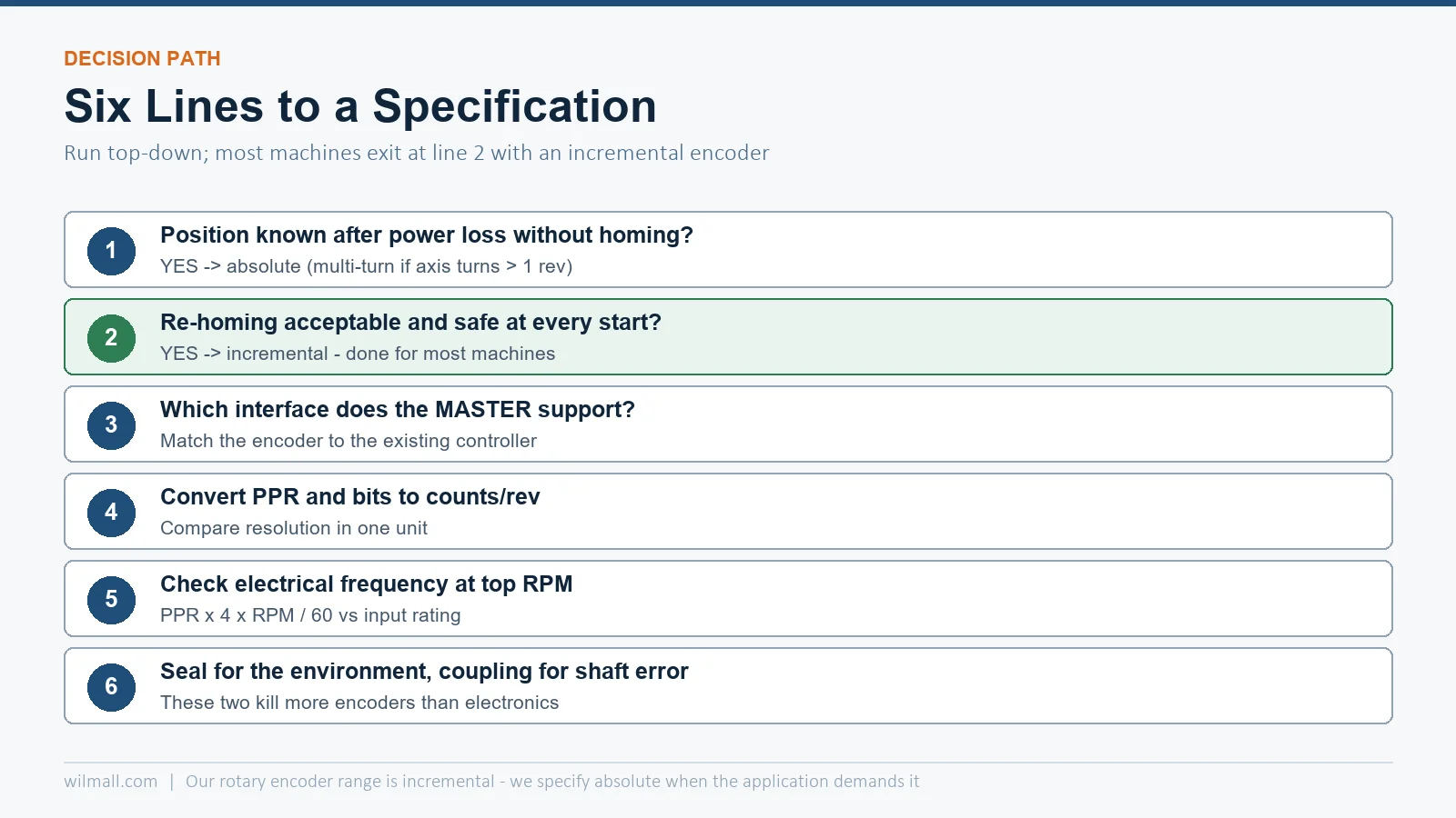 ” />
For the applications where the path lands on incremental — the large majority of speed loops, counting tasks and homed axes — our 38 mm and 45 mm series such as the GOS38A04 heavy-duty shaft encoder and the GOS38D carry the standard industrial option set: 100–2500 PPR, line driver or push-pull output, IP65 housings. Browse the full range in the rotary encoder category, and for the symbol and wiring conventions on drawings, encoder symbol and wiring guide.
Only within one power cycle, after homing. With a battery-backed counter module the count can survive power loss, but that moves the criticality from the encoder to the counter — an absolute encoder is the cleaner engineering answer when retention is required.
If the screw rotates more than one revolution across full travel and the axis cannot re-home, yes — single-turn absolute would report the same angle at multiple physical positions. Check the multi-turn range against the screw’s total revolutions with margin.
With quadrature ×4 decoding it is 10,000 counts per revolution, or 0.036° per count. Mechanical accuracy also depends on coupling quality, backlash and the mechanics — the encoder count is a ceiling, not a guarantee.
Emergency stop circuits often cut control power, which erases the accumulated count. If the machine must resume exactly where it stopped, either keep the counter powered through the stop (with a safe-speed restart procedure) or move that axis to an absolute encoder.
Neither categorically. Incremental units have fewer components and a simpler interface; absolute units remove the homing switch and reference cycle from the failure inventory. Reliability is decided by sealing, coupling and environment far more than by the encoding principle.