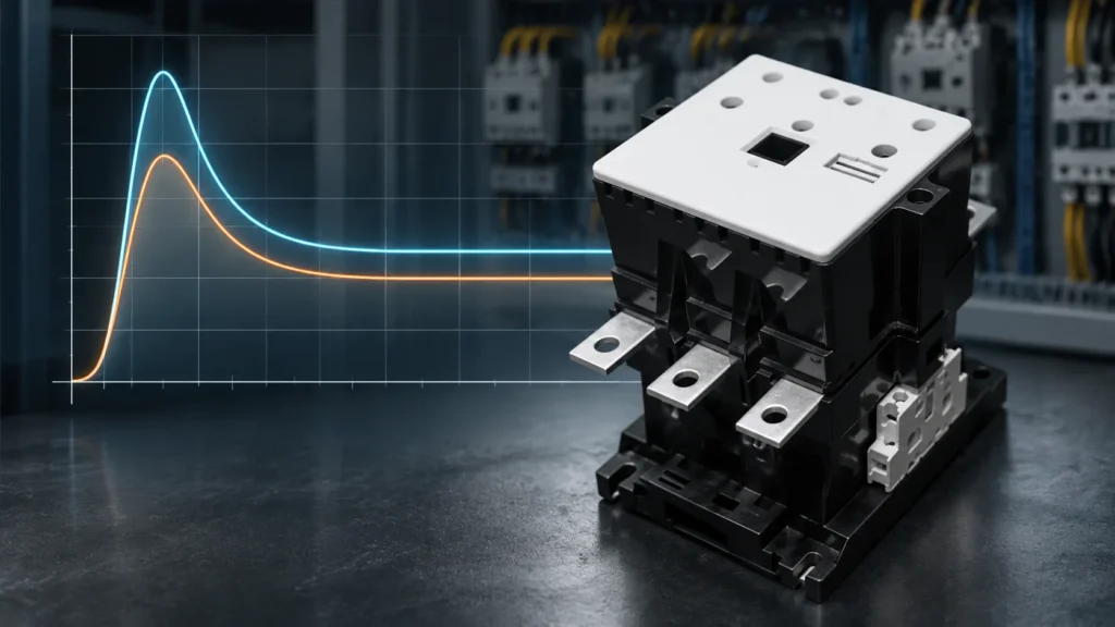
A contactor coil draws two very different amounts of power: a short inrush while the armature is still open (typically 6–15× the holding value — about 70 VA against 8 VA on a 12 A frame at 220 V), then a small sealed VA once the magnetic circuit closes. Size every switching device, control fuse and the control transformer on inrush VA; size the continuous heat load on sealed VA. IEC 60947-4-1 requires the contactor to close reliably anywhere between 85 % and 110 % of rated control voltage and to release between 20 % and 75 % (AC coil).
If you have ever watched a PLC output card weld itself shut the first time it pulled in a “tiny” contactor coil, or a panel of contactors chatter every Monday morning startup, you have met the gap between the two numbers on the coil datasheet. This article walks through what inrush VA and sealed VA actually measure, typical values by frame size, what the numbers mean for fuses and control transformers, and where the 85 %/75 % voltage window comes from.
Two Numbers, Two Jobs: What Inrush VA and Sealed VA Measure
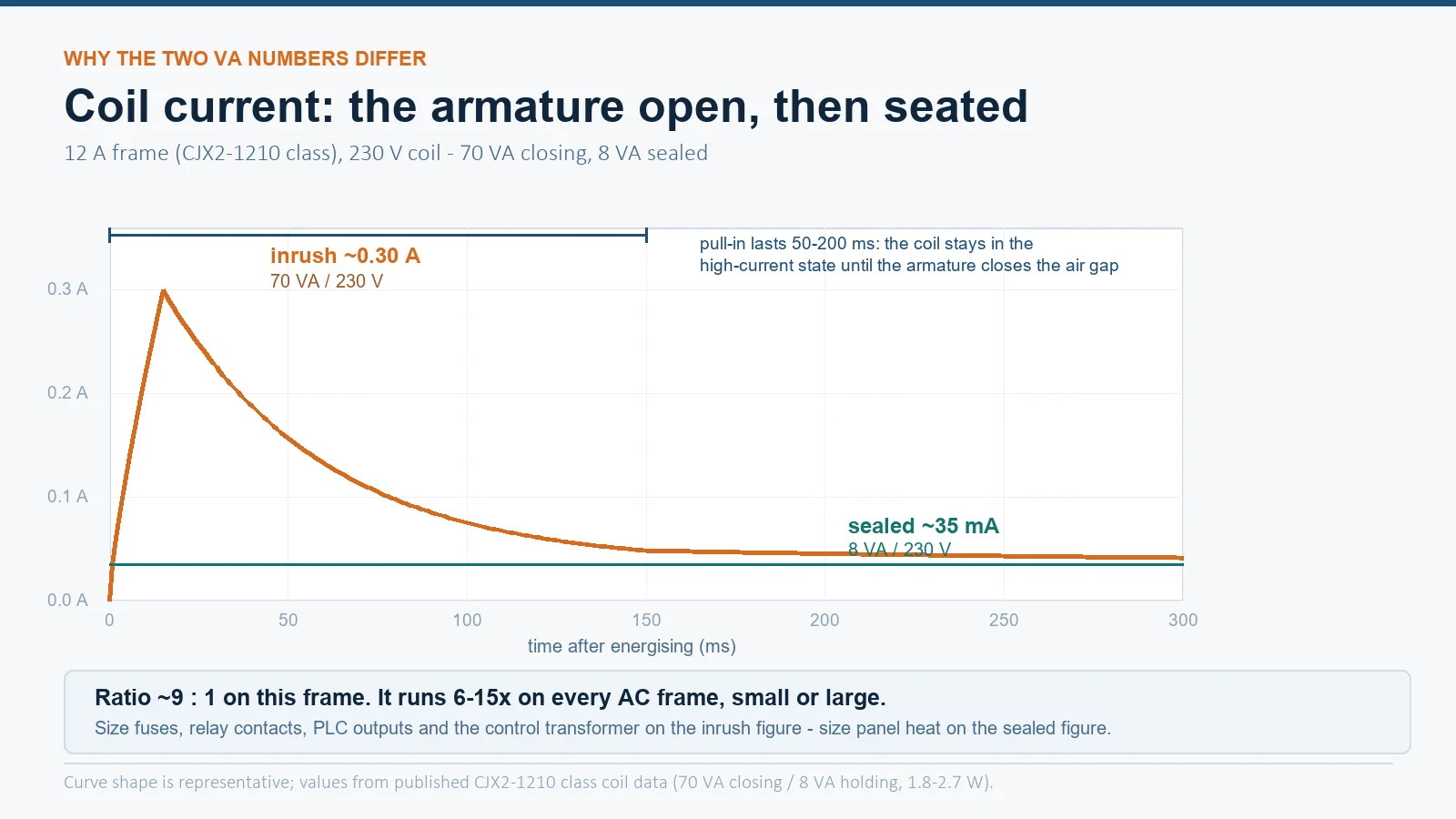
Every AC contactor datasheet lists coil consumption twice, and the two figures are not close. A typical catalog line reads something like closing 70 VA, holding 8 VA, coil loss 1.8–2.7 W for a CJX2-1210 (12 A AC-3) with a 220 V coil. The same pattern holds across brands: an inrush figure several times larger than the sealed figure, both quoted in volt-amperes because the coil current is far from sinusoidal during pickup.
- Inrush (closing) VA — the apparent power the coil draws in the first few cycles, while the armature is still travelling. It lasts roughly 50–200 ms on small frames.
- Sealed (holding) VA — the continuous draw once the armature is seated against the pole faces and the coil settles to steady state. This is the number that heats the coil and the panel.
The two numbers do two different jobs. Inrush VA sizes everything that switches or feeds the coil: the relay or PLC output contact, the control fuse, the control transformer secondary. Sealed VA sizes everything that must carry the coil continuously: the thermal load in the enclosure, the standing load on the control supply. Confusing the two is the single most common coil-sizing mistake in the field — engineers read the 30 mA holding current, assume 16× margin on a 0.5 A output, and then wonder why a solid-state output trips on the very first pickup.
Typical Coil Consumption by Frame Size
Published catalog values make the pattern concrete. The figures below are typical manufacturer-published values for widely used IEC frames; always confirm against the datasheet of the exact coil voltage you order, because the VA figures change with voltage and frequency.
| Contactor frame (AC-3 Ie) | Sealed VA (typical) | Inrush VA (typical) | Inrush : sealed ratio |
|---|---|---|---|
| 9–12 A (e.g. CJX2-1210) | ~8 VA | ~70 VA | ~9 : 1 |
| 18–32 A | ~9–10 VA | ~80–110 VA | ~8–11 : 1 |
| 40–65 A | ~26 VA | ~200–260 VA | ~8–10 : 1 |
| 80–95 A | ~27–30 VA | ~250–300 VA | ~9–10 : 1 |
| Large frame, 115 A+ | 30–80 VA | 300–700 VA | 6–15 : 1 (varies widely) |
Two things stand out. First, the ratio stays roughly in the 6–15× band across the whole range — it does not shrink as frames get bigger. Second, the sealed VA of the big frames is not dramatically higher than the small ones (the coil runs a more efficient magnetic circuit once seated), but the inrush scales with frame size, which is exactly what the control transformer feels at startup.
Why the Ratio Exists: The Air Gap in the Magnetic Circuit
The physics is simple and worth knowing, because it explains why the ratio cannot be “fixed” with a better coil. An AC coil is essentially an inductor whose impedance depends on the magnetic circuit. With the armature open, the flux path includes an air gap of a few millimetres. Air has essentially no permeability compared with silicon steel, so the coil’s inductance is low and the magnetizing current is high — that is the inrush. As the armature closes, the air gap disappears, inductance rises sharply, and current falls to the small sealed value.
This also explains two field observations:
- A coil that hums and draws high current usually has a mechanical problem. If dirt, a burr, or a failed shading ring prevents the armature from seating fully, the coil never leaves the high-current state. The coil overheats and the contactor chatters — the failure looks electrical but the root cause is mechanical. Our article on why contactors buzz covers the diagnosis.
- Inrush is not a capacitor-style transient. It persists for as long as the armature takes to close. A slow or sticking mechanism means a longer inrush period, not just a bigger peak.
From VA to Amps: What the Control Circuit Actually Sees
Convert the VA figures to currents so the fuse and wire sizing becomes concrete. Take the verified CJX2-1210 example on a 230 V control supply:
- Inrush current: 70 VA ÷ 230 V ≈ 0.30 A for the first 50–200 ms.
- Sealed current: 8 VA ÷ 230 V ≈ 35 mA continuous.
- Coil heat: 1.8–2.7 W dissipated continuously inside the panel.
Practical consequences:
- Control fuses must be sized to ride through 0.30 A for 200 ms without blowing, yet still protect the wiring. A time-delay (class T or aM) characteristic, or simply a fuse rated above the inrush with the wiring sized for it, is the normal answer.
- Relay and PLC outputs must be selected on inrush. A 0.5 A resistive rating covers 35 mA holding with a huge margin but only 1.6× the inrush peak — and solid-state outputs often have much tighter inrush ratings than resistive ones.
- Control wiring to the coil is sized on inrush too, but on small frames the sealed current dominates the heat calculation; 0.75–1 mm² control cores handle a dozen small coils comfortably.
Voltage Tolerance: The 85 % Pickup and 75 % Drop-out Window
IEC 60947-4-1 defines the operating window that every compliant contactor must meet, and it is the window your control supply must stay inside:
| Condition | AC coil | DC coil | What it means |
|---|---|---|---|
| Must reliably close | 85–110 % of Us | 85–110 % of Us | Below 85 % the armature may not complete its travel |
| Must remain closed | down to the release band | down to the release band | Ride-through of dips while running |
| Must release | 20–75 % of Us | 10–75 % of Us | Guaranteed drop-out below 20 % (AC) / 10 % (DC); must NOT drop out above 75 % |
The drop-out band is the part people misread. The contactor is permitted to release anywhere between 75 % and 20 % — so a design that relies on the contactor holding through a dip to exactly 74 % is gambling on a value the standard does not guarantee. The failure mode when pickup happens at marginal voltage is nastier than a simple no-start: the armature hovers, contacts make and break repeatedly, and the contactor chatters, burning tips and generating enough EMI to upset nearby drives.
This is why control-supply regulation is part of the design, not an afterthought. A long control cable with significant volt-drop, a control transformer sagging under simultaneous inrush, or several contactors picking up together can all pull the coil voltage into the chatter zone even though the supply side reads a healthy 230 V. If your panels see frequent coil problems, our guide to coil voltage markings and the coil test procedure cover the measurement side.
Sizing the Control Transformer for Inrush, Not Nameplate
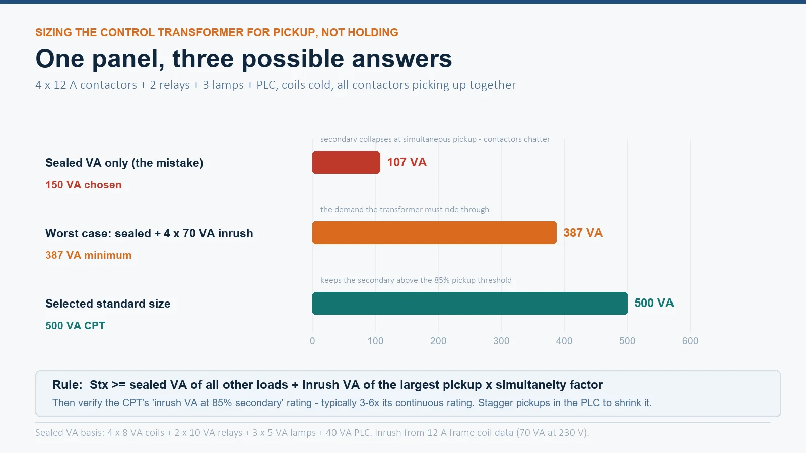
Here is where the money is. A control transformer does not need to supply the sum of sealed VA values — it needs to ride through the worst-case simultaneous inrush without the secondary sagging below the 85 % pickup threshold. The working rule (NEMA ICS 1 and general industry practice):
Stx ≥ Σ(sealed VA of all other loads) + (inrush VA of the largest coil × simultaneity factor)
Worked example — a small machine panel:
- 4 × CJX2-1210 coils, sealed 8 VA each = 32 VA; largest single inrush = 70 VA.
- 2 × auxiliary relays at 10 VA sealed = 20 VA.
- 3 × LED pilot lights at 5 VA = 15 VA; PLC power supply 40 VA.
- Continuous (sealed) total: 32 + 20 + 15 + 40 = 107 VA.
- Worst case: all four contactors pick up together after a power dip: 107 + (70 × 4) = 387 VA peak.
| Sizing basis | Result | Outcome in service |
|---|---|---|
| Sealed VA only (the classic mistake) | 107 VA → a “150 VA” transformer | Voltage collapses at simultaneous pickup; chattering contactors on every restart |
| Sealed + simultaneous inrush | 387 VA → 500 VA standard size | Secondary stays above 85 % during pickup; clean starts |
One more catch: you cannot read the nameplate VA of the transformer and assume it supports that much inrush. Control transformers are rated for regulation, and their published “inrush VA at 85 % secondary” is typically 3–6× the continuous rating. If the inrush rating is not published, continuous VA × 4 is a reasonable estimate for machine-tool-grade open-frame units. Spacing pickups 100–150 ms apart in the PLC is a legitimate way to shrink the transformer — it is cheaper than the VA.
AC vs DC Coils: Where Inrush Does Not Apply
DC coils behave differently in one important way: the current is set by winding resistance, not by an air-gap-dependent inductance, so the coil draws the same current with the armature open and closed. There is no inrush signature, which is why a DC coil’s datasheet usually quotes a single VA or W figure plus the coil resistance.
The trade-offs are covered in detail in our AC vs DC contactor comparison, but for power consumption the summary is:
- AC coil: low holding power, high inrush, needs an AC-rated control supply and inrush-aware transformer sizing.
- DC coil (raw): high continuous draw (the sealed current equals the pickup current), so larger frames add an electronic economizer that cuts holding power after pickup.
- DC coil switching: remember that interrupting the coil current on DC is harder on the switching contact than AC, because there is no natural current zero.
Heat: What Sealed VA Costs You in Continuous Duty
Sealed VA is the number your enclosure thermal calculation cares about. Multiply by the coil power factor (published as coil loss in W on good datasheets — 1.8–2.7 W for the 12 A frame in our example, rising to 8–10 W at 95 A) and you have the continuous heat injected into the panel. A panel with twenty energized coils is a small space heater running 24/7, which is why coil consumption matters for panel cooling sizing in hot climates — and why the electrically-held vs latched distinction on lighting contactors (zero holding VA when latched) is worth considering for continuously-energized circuits.
Two practical notes for procurement:
- Coil consumption changes with voltage tap and frequency. A 50 Hz coil run on 60 Hz (or vice versa) shifts both the impedance and the VA figures; always order the coil voltage/frequency matched to the control supply, and see our utilization category guide for how the main-circuit side of the same datasheet works.
- If your application switches coils through electronic outputs or needs guaranteed low holding draw, ask for the coil VA table for the exact reference — for example the 3TF series electromagnetic AC contactors publish inrush/holding figures per frame, and we can supply the coil data sheet with the offer.
Frequently Asked Questions
How many times bigger is the inrush than the holding current on a contactor coil?
Typically 6–15× for AC coils. A 12 A frame at 220 V drawing about 70 VA inrush and 8 VA sealed is roughly 9×. The ratio is largest on small frames and varies with brand and frequency, so always use the datasheet pair for your exact coil.
Why does my contactor coil get hot even though it draws only milliamps?
The sealed VA is small, but it is continuous. 2–3 W of coil loss dissipates into the enclosure all day; in a sealed panel in a hot climate this adds up across every energized coil. Heat above the coil’s temperature class, or a coil that never fully seals because of a mechanical fault, is what actually burns coils.
Can I size the control transformer on the sealed VA total?
No. The transformer must ride through worst-case simultaneous inrush without the secondary dropping below 85 % of coil rated voltage, or contactors will chatter at startup. Use sealed VA + largest inrush VA (with a simultaneity factor), then check the transformer’s published inrush VA at 85 % — typically 3–6× its continuous rating.
What happens if coil voltage drops below 85 % during pickup?
The armature may not complete its travel: contacts touch and break repeatedly (chatter), tips burn, and the coil stays in its high-current state. Below the release threshold the contactor drops out entirely. Both are control-supply design problems, not contactor defects.
Do DC contactor coils have inrush?
No. Current is set by winding resistance and is the same open or closed — that is why large DC coils use economizer circuits to cut holding power. The sizing burden moves from the transformer to the continuous supply capacity and to the switching contact, which must break a DC arc.