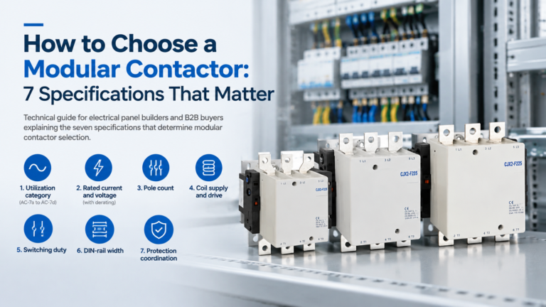
How to Choose a Modular Contactor: 7 Specifications That Matter
Seven specifications decide whether a modular contactor survives or fails: utilization category, current and derating, poles, coil supply, duty, rail space and protection.
Read More
The choice between alternating current (AC) and direct current (DC) is the difference between AC vs DC control circuits.
This article provides a systematic comparison of AC- and DC-powered control circuits across four dimensions: operational reliability during fault conditions, electromechanical switching performance, system complexity and lifecycle cost, and safety considerations.
DC control systems—typically operating at 110 V or 220 V from dedicated battery banks—offer decisive advantages in protection dependability and autonomy during AC network collapse.
AC control circuits, simpler and less capital-intensive, introduce a fundamental dependency that can disable protection schemes precisely when they are most needed.
We hope this article can help buyer about the engineering boundary conditions under which each approach is appropriate.
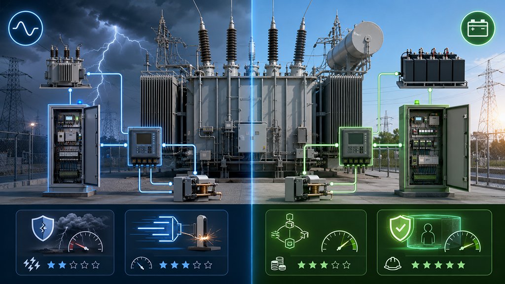
Power transformers are the most capital-intensive single assets in electrical substations, and their protection systems are designed with an uncompromising mandate: to detect and isolate faults before catastrophic damage occurs.
The auxiliary circuits that energise protection relays, circuit-breaker trip and close coils, interlocking logic, annunciation panels, and supervisory control and data acquisition (SCADA) interfaces are collectively referred to as the control circuit.
The choice of voltage type—AC or DC—for these circuits is not a trivial detail but a foundational architectural decision that determines whether protection remains functional during the very contingency it exists to address.
The historical trajectory of this choice reflects an evolving understanding of system reliability.
Early substations in the first half of the twentieth century often employed AC control circuits, sourced conveniently from station service transformers or tertiary windings.
As power systems grew in complexity and fault currents increased, the vulnerability of this arrangement became apparent: a severe fault that depresses or collapses the AC bus voltage simultaneously deprives protection relays and trip coils of their operating power, creating a dangerous single-point-of-failure that links the health of the protection system to the very fault it must clear.
This realisation drove the wholesale migration to battery-backed DC control systems in transmission-class substations from the 1960s onward, a transition codified in international grid codes and utility design standards.
Nevertheless, AC control circuits have not disappeared.
They persist in distribution-level switchgear, in certain industrial applications where cost sensitivity outweighs reliability requirements, and in legacy installations that have demonstrated decades of acceptable performance.
Moreover, the proliferation of intelligent electronic devices (IEDs) and the convergence of operational technology with information technology have introduced new considerations: modern digital relays accept universal AC/DC power supplies, communication networks carry their own power constraints, and the lifecycle cost of battery maintenance has become a non-trivial operational burden.
This has reopened the comparison on new terms.
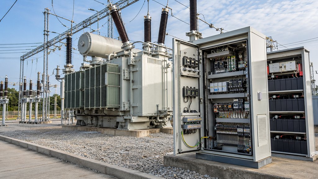
A transformer control circuit encompasses all low-voltage auxiliary wiring and apparatus that perform monitoring, protection, and switching functions.
The principal loads served include:
Collectively, these loads constitute the “nervous system” of the substation.
Their power supply architecture must guarantee availability under all credible operating scenarios, including the fault conditions that the protection system itself is designed to address.
In an AC control scheme, auxiliary power is derived from the same AC network that the transformer serves, typically through a station auxiliary transformer connected to the tertiary winding or a separate distribution feeder.
The nominal control voltage is commonly 110 V or 230 V AC, single-phase. Where continuity is required, an uninterruptible power supply (UPS) may be interposed, consisting of a rectifier, battery bank, and inverter that reconstructs an AC waveform from stored DC energy during mains interruption.
The key architectural characteristic of this approach is its dependence on the AC network.
Even when a UPS is present, the inverter represents an active electronic element whose mean time between failures (MTBF) is substantially lower than that of a passive battery-and-distribution DC system.
Furthermore, the waveform quality of UPS output—harmonic content, voltage regulation under step loads, and transient response—can affect the performance of sensitive electronic relays.
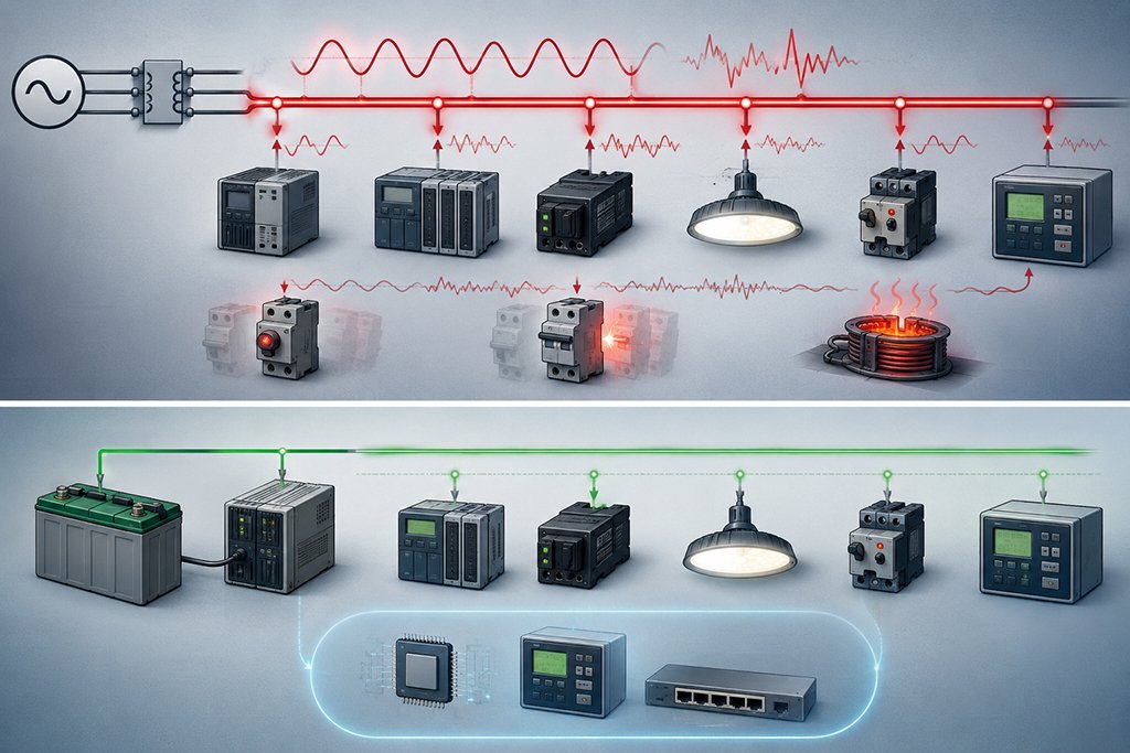
DC control circuits are powered by a dedicated battery bank maintained in a float-charged state by a rectifier/charger connected to the AC auxiliary supply.
Under normal conditions, the charger supplies the DC load while maintaining the battery at full charge.
Upon loss of AC input, the battery seamlessly assumes the load without any switching transient, providing uninterrupted DC power for a designed autonomy period—typically 8 to 24 hours, sufficient for operator intervention or restoration of the AC supply.
The DC distribution system is straightforward: fuses or miniature circuit breakers protect individual feeders radiating from a DC distribution panel to relay panels, circuit-breaker control circuits, and auxiliary loads.
The absence of rectifiers, inverters, or waveform-shaping stages in the power delivery path confers an intrinsic simplicity and robustness.
Standard DC control voltages include 24 V (small automation systems), 48 V (telecommunications), 110–125 V (industrial plants and medium-sized substations), and 220 V (large transmission substations with long control cable runs).
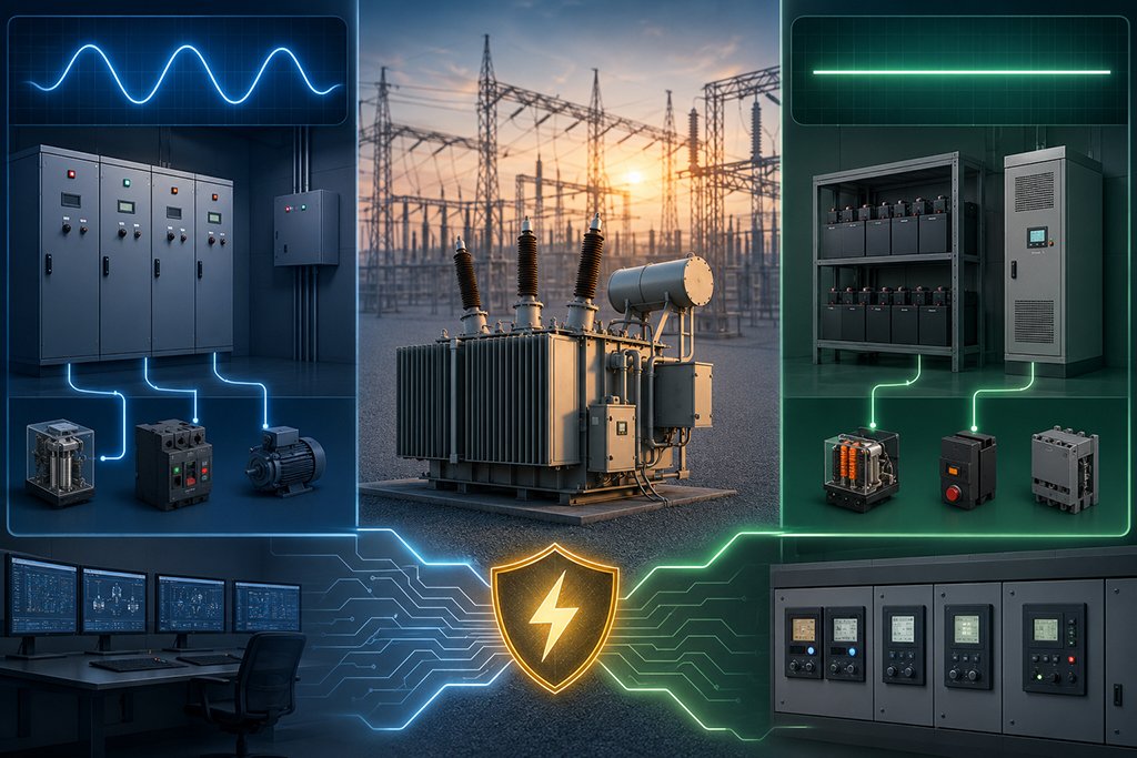
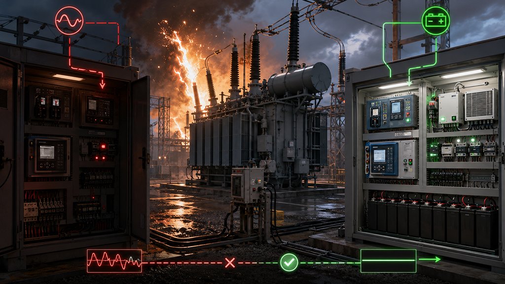
When a transformer experiences an internal winding fault, a busbar fault, or a through-fault from a downstream network disturbance, the AC supply voltage may sag to a fraction of its nominal value or collapse entirely.
If the control circuit draws its power from this same AC source, the protection relays lose their operating voltage at the very instant they are required to issue a trip command.
This failure is particularly acute for electromechanical relays, which may chatter or reset during voltage dips, but digital relays are also vulnerable: while many incorporate hold-up capacitors that sustain operation for tens of milliseconds, a sustained voltage collapse beyond this ride-through window will cause a reboot, during which the relay is blind.
DC systems, are galvanically decoupled from the AC network through the battery-charger interface.
The battery bank acts as an energy reservoir; its terminal voltage decays gradually as the battery discharges, providing ample time for the protection scheme to operate and for operators to respond.
The system responsible for detecting and clearing faults cannot rely on the same power source that may be damaged by the fault. And DC systems’ architectural independence is the reason for its existence.
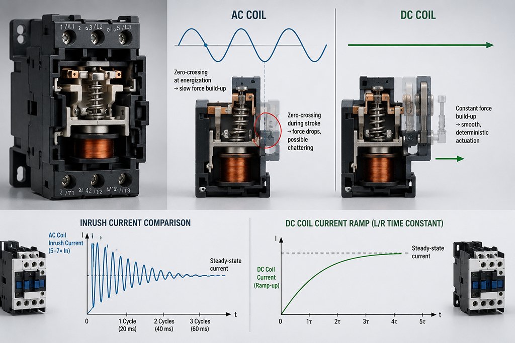
The physics of coil actuation differs materially between AC and DC supplies, with direct consequences for the speed and reliability of circuit-breaker operation.
When an AC voltage energises a circuit-breaker trip or close coil, the current through the coil is governed by the combined impedance of resistance and inductive reactance.
At the instant of energisation, if the voltage waveform happens to be near its zero-crossing point, the initial rate of current rise is limited, and the magnetic force on the plunger may be insufficient to initiate movement.
If the voltage crosses zero during the plunger stroke—which it will, at 100 or 120 crossings per second—the magnetic field momentarily approaches zero, and the spring-loaded mechanism may experience a partial release (chattering) before the next half-cycle restores the field.
This effect, while mitigated by the mechanical inertia of the moving parts and by the presence of shading rings in AC-specific contactor designs, introduces a time uncertainty of up to half a cycle (10 ms at 50 Hz) in the actuation sequence.
How about DC coils?
The applied voltage is constant, the current rises according to the L/R time constant of the coil, and the magnetic force builds monotonically until the plunger completes its stroke.
The actuation is deterministic, free of zero-crossing interruptions, and reliably fast.
In fault-clearing applications, where every millisecond of delay increases the thermal and mechanical stress on equipment, this determinism is of tangible value.
Furthermore, the inrush current characteristic differs: AC coils draw 5–7 times their steady-state current during the first few cycles due to the low initial impedance of the open magnetic circuit, potentially causing voltage dips on the control bus that affect neighbouring equipment.
DC coils, while also exhibiting an inrush transient, impose a smoother current ramp that is less disruptive to the common DC bus.
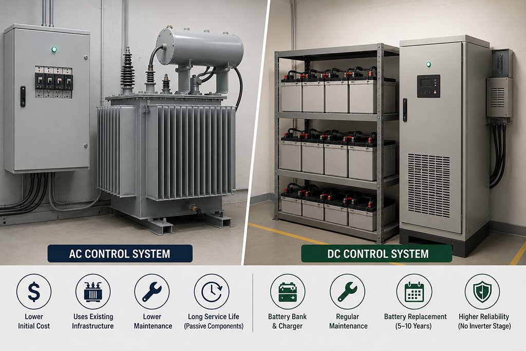
AC control circuits present a lower first cost. The absence of a battery bank, charger, and DC distribution panel eliminates several line items from the procurement budget.
Station service transformers already exist for lighting, HVAC, and motor loads; extending their reach to the control circuits incurs only the marginal cost of additional wiring and protection devices.
In distribution substations where a site battery is not mandated by the grid code, this simplicity can represent a meaningful cost saving.
However, when an AC scheme incorporates a UPS to address the single-point-of-failure concern, the first-cost advantage narrows considerably and may reverse.
A UPS of sufficient rating to support all control loads for the required autonomy period includes a battery bank, a rectifier, an inverter, a static bypass switch, and ventilation or air-conditioning to manage the inverter’s heat dissipation.
Les inverter is a power-electronic assembly with an MTBF typically in the range of 50,000–100,000 hours (6–11 years), requiring periodic replacement of electrolytic capacitors and cooling fans.
The DC equivalent eliminates the inverter stage entirely, achieving higher reliability with fewer active components.
Maintenance costs represent the principal lifecycle burden for DC systems.
Lead-acid battery banks require quarterly inspections, semi-annual electrolyte-level checks and specific-gravity measurements, periodic discharge testing, and replacement every 5–10 years depending on operating temperature and cycling history.
Valve-regulated lead-acid (VRLA) and nickel-cadmium (Ni-Cd) chemistries reduce but do not eliminate this maintenance.
AC systems, particularly those without a UPS, impose substantially lower maintenance demands.
The station service transformer is a passive device with a service life comparable to the main power transformer, and the AC distribution panels require only periodic thermal imaging and insulation resistance testing.
This disparity in maintenance intensity is the principal reason AC control persists in lower-tier substations and industrial installations.
| Criterion | AC Control | DC Control |
|---|---|---|
| Operation during AC loss | Fails without UPS; dependent on inverter with UPS | Seamless battery takeover; no switching transient |
| Trip coil actuation | Zero-crossing uncertainty (≤10 ms); potential chattering | Deterministic, monotonic force build-up |
| Initial capital cost | Low (no battery/charger) | Moderate (battery, charger, DC panel) |
| Annual maintenance | Minimal (thermal scan, IR testing) | Moderate–high (battery inspection, testing, replacement) |
| Component count (active) | Low (without UPS); high (with UPS inverter) | Low (charger only; no inverter required) |
| Harmonic susceptibility | Moderate (AC bus harmonics affect relays) | Negligible (DC bus is inherently harmonic-free) |
| Fault-finding ease | High (neutral referenced to earth; standard testers) | Moderate (floating or impedance-earthed; DC-specific instruments) |
| Long-distance cable performance | Voltage drop affected by line inductance | Voltage drop purely resistive; more predictable |
| Grid code acceptance | Distribution only; rarely permitted at transmission | Universal at transmission; mandated by most grid codes |
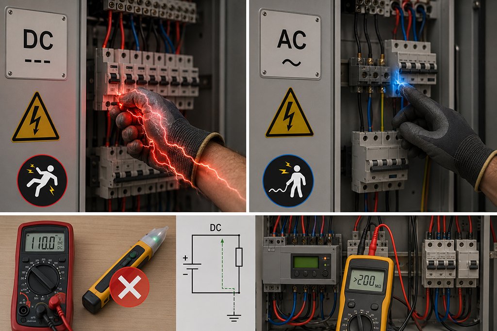
DC systems present a higher electric-shock hazard at equivalent voltage levels.
The sustained, non-alternating nature of DC current causes continuous muscle contraction (the “can’t let go” effect), increasing the risk of prolonged exposure during accidental contact.
AC at power frequency, while also dangerous, induces periodic muscle relaxation at zero crossings, which can facilitate self-extraction.
This difference has motivated the adoption of 110 V DC (rather than, say, 230 V DC) as the standard control voltage in many jurisdictions, balancing the competing demands of safety and long-cable voltage drop.
Standard non-contact voltage testers (voltage pens) are designed for AC electric fields and do not respond to DC.
Troubleshooting a DC control circuit requires a multimeter or dedicated DC voltage tester, and DC circuits in substations are typically operated with a floating or high-impedance-earthed configuration to maintain continuity of supply during a single earth fault.
This means that a simple “neutral-to-earth” measurement—a staple of AC fault-finding—is unavailable; an insulation monitoring device or deliberate earth-fault-locating procedure must be used instead.
AC control buses are subject to the same harmonic distortion that affects the broader AC network.
Non-linear loads within the substation—battery chargers, switch-mode power supplies in digital relays, LED lighting drivers—inject harmonic currents that distort the voltage waveform.
High harmonic content can cause relay maloperation, spurious tripping of residual-current devices, and overheating of AC coil windings.
The DC bus, sourced from a battery with a charger that incorporates filtering, is inherently free of harmonic content.
The charger’s output filtering attenuates residual ripple to a few percent, and the battery itself acts as an enormous capacitor that further smooths the DC voltage.
This electromagnetic cleanliness is advantageous for the increasingly prevalent microprocessor-based relays and communication equipment that populate modern control panels.
The dichotomy between pure AC and pure DC control is being blurred by technological developments in two directions: the increasing sophistication and reliability of power-electronic converters, and the adoption of IEC 61850 process-bus architectures that fundamentally change the topology of control power distribution.
Rather than distributing 110 V or 220 V DC from a central battery to every bay, modern substations can employ a distributed DC architecture in which a central battery supplies a higher DC bus voltage (e.g., 220 V), and point-of-load DC-DC converters step this down to the voltage required by each IED (typically 24 V or 48 V).
This decouples the distribution voltage (optimised for long cable runs) from the utilisation voltage (optimised for electronic loads) and allows smaller-gauge control cabling.
The converters also provide galvanic isolation between bays, improving fault containment.
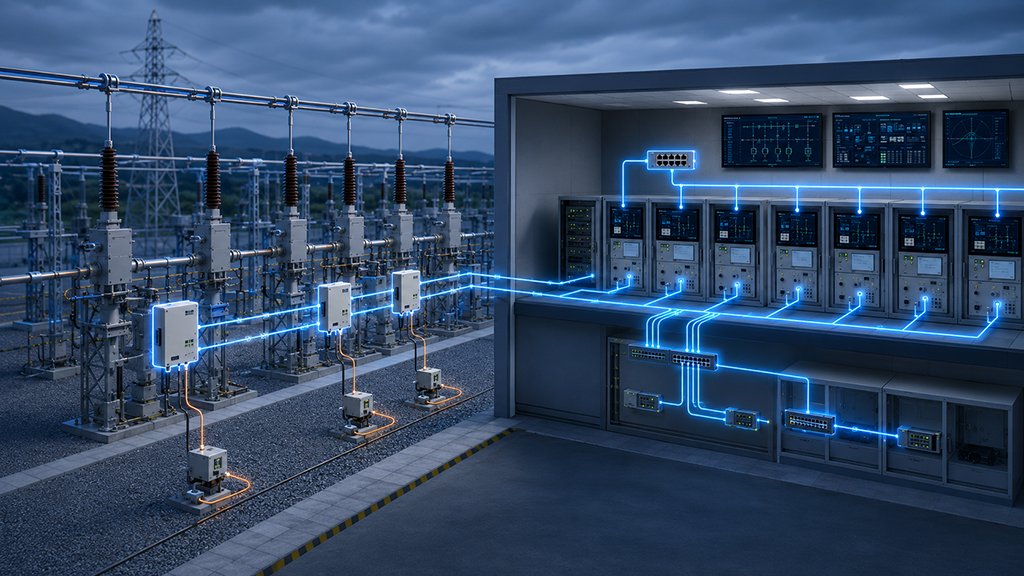
The IEC 61850 standard envisions a substation in which hardwired copper control cables are progressively replaced by fibre-optic Ethernet links.
In the fully realised process-bus architecture, merging units at the switchyard collect analogue current and voltage signals and digitise them at source; generic object-oriented substation event (GOOSE) messages carry trip and interlock commands; and sampled values (SV) streams replace traditional CT and VT secondary wiring.
This architecture does not eliminate the need for a reliable power supply for the merging units and circuit-breaker trip coils in the yard, but it does change the nature of the loads.
Optical fibres require no power, so the control-house-to-yard power distribution becomes dedicated purely to energising a small number of electronic devices and trip coils at each bay.
This simplifies the DC distribution task and, paradoxically, may reinforce the case for DC, since the merging units themselves require clean, reliable DC power to function.
A merging unit whose AC-derived supply fails during a fault is as useless as a hardwired relay with the same vulnerability.
An innovative topology that partially rehabilitates AC control employs a solid-state relay (SSR) in parallel with the circuit-breaker coil. In this arrangement, the SSR (typically a TRIAC-based device) is triggered at the zero-crossing of the AC waveform to energise the coil, eliminating inrush transients and zero-crossing chattering.
A conventional electromechanical relay then closes and shunts the SSR during steady-state conduction, reducing thermal stress on the semiconductor.
Les SSR conducts for only 50–100 ms during each switching event, allowing a compact, heatsink-free design.
While this hybrid approach addresses the electromagnetic performance drawbacks of AC control, it does not resolve the fundamental dependency on the AC source during fault conditions.
It is therefore best suited to applications where cost constraints preclude a full DC installation but where the switching duty is frequent enough to justify the additional complexity of the hybrid circuit.
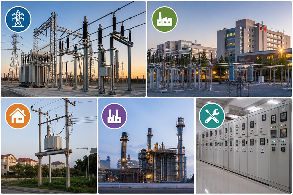
The following decision heuristics, derived from the preceding analysis, are offered as practical guidance for substation design engineers:
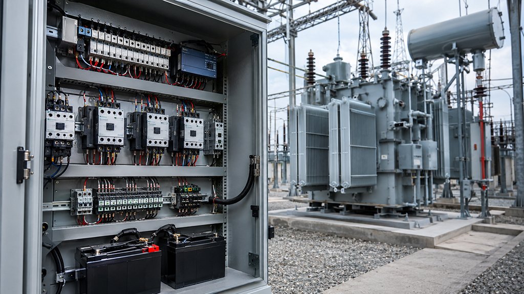
The independence of a battery-backed DC supply from the AC network it protects, the deterministic electromagnetic performance of DC coils, the simplicity of a charger-and-battery architecture compared with a UPS inverter chain, and the harmonic cleanliness of the DC bus collectively constitute a compelling engineering case.
However, its battery maintenance imposes a recurring operational burden that must be resourced and managed, and the higher first cost of a DC installation may be difficult to justify in the least critical tiers of the distribution network.
AC control, particularly when implemented without a UPS, offers simplicity that translates into lower lifecycle overhead for applications where the consequences of protection failure are statistically and economically tolerable.
Looking forward, two trends are likely to reshape this comparison. First, the maturation of lithium-ion battery technology, with its longer cycle life, reduced maintenance, and declining cost, will progressively erode the maintenance-cost disadvantage of DC systems.
Second, the migration toward IEC 61850 process-bus architectures, with their concentration of yard-mounted electronics requiring clean, reliable DC power, may paradoxically broaden the application scope of DC control while reducing the amount of copper it must energise.
The enduring principle remains unchanged: the circuit that protects the transformer must outlive the fault.
DC control circuits are preferred because their battery-backed power supply remains available even when the main AC network experiences a voltage sag or complete outage.
This allows protection relays, trip coils, interlocking circuits, and control equipment to continue operating during serious electrical faults.
For transmission substations and facilities supplying critical loads, this independence significantly improves protection reliability and fault-clearing capability
An AC control circuit may be suitable for non-critical distribution systems, commercial installations, and industrial applications where the consequences of a temporary control-power failure are limited.
AC systems generally have a lower initial cost and require less battery maintenance.
However, engineers should carefully evaluate whether the control circuit must remain operational during a loss of the main AC supply.
An AC coil operates with an alternating magnetic field and may experience inrush current, zero-crossing effects, vibration, or chattering when the control voltage is unstable.
A DC coil receives constant voltage, producing a smoother and more predictable magnetic force.
This makes DC coils particularly suitable for applications where reliable and repeatable switching is essential.
The coil voltage must always match the control power supply specified for the contactor, relay, or circuit-breaker operating mechanism.
A DC control system normally includes a battery bank, charger, DC distribution panel, protective devices, and monitoring equipment.
The batteries require periodic inspection, capacity testing, terminal checks, and eventual replacement.
Although this increases maintenance requirements, the battery provides an independent source of control power during AC supply failures.
By comparison, an AC control circuit without a UPS is simpler to maintain but cannot provide the same level of power-supply independence.
Start by checking the motor rated current, operating voltage, coil voltage, number of poles, utilization category, switching frequency, and required auxiliary contacts.
For standard motor starting and stopping, the AC-3 rating is normally the key selection reference.
For frequent reversing, plugging, or inching applications, the more demanding AC-4 operating conditions must be considered.
The contactor coil voltage must also match the AC control circuit, such as 24 VAC, 110 VAC, 220 VAC, or another specified voltage.
You can explore WILMALL’s AC contactors for motor control and industrial switching
to compare CJX2, LC1-D, 3TF, and other contactor series.
Yes. WILMALL supplies multiple AC contactor series for motor starting, main-circuit switching, industrial automation, and power-distribution applications
Available options include LC1-D contactors, CJX2 contactors, CJX2-F high-current contactors, 3TF series contactors, mechanical interlocking contactors, and replacement contact kits for CJX2, CJX4, and CJ35 contactors.
Distributors and industrial buyers can also request bulk pricing, OEM/ODM production, private labeling, and specification customization.