Reversing Contactor Wiring: Electrical and Mechanical Interlock Done Right
Published: Author: Lisa
Reversing contactor wiring looks like a two-contactor swap exercise until you consider what happens in the 50 milliseconds when one contactor has not finished opening and the other starts to close. Two phases of a three-phase supply meeting across a closing contact pair is a bolted short circuit — and the interlock chain, not the operator’s reflexes, is what prevents it.
This guide walks the standard forward-reverse circuit: the power wiring, the electrical interlock that makes wrong sequencing impossible, the mechanical interlock that backstops it, the switching dead time, and the weld-detection logic that no interlock can provide. The device-level differences between reversing, latching, and vacuum types are surveyed in the latching, reversing and vacuum contactors guide; here we stay on wiring.
Quick Answer: The Rules That Make Reversing Safe
Rule
What it prevents
How it is implemented
Electrical interlock
Both coils energized simultaneously via control logic error
Each contactor’s coil circuit passes through the other contactor’s NC auxiliary contact (cross-coupled 21–22 contacts)
Mechanical interlock
Both contacts closing even with a welded coil, spring fault, or manipulated circuit
Factory-fitted interlock kit physically bars both armatures from seating at once
Switching dead time
Arc overlap and plugging-current shock on fast direction changes
0.05–0.1 s timer or deliberate two-press sequence (stop, then reverse)
Overload protection on the load side
Thermal damage during plugging or stalled reversal
One overload relay downstream of both contactors, or one per contactor per the starter design
Weld detection (where required)
Phase-to-phase fault through a welded pole pair
Voltage-sensing relay or auxiliary feedback verifying a contactor has actually opened before the opposite coil is enabled
The electrical and mechanical interlocks are not redundant — they defend against different failures. The electrical interlock stops logic errors; the mechanical interlock stops physics. Use both on every reversing starter.
Power Wiring: Two Phases Swapped, One Phase Common
Reversal of a three-phase motor requires swapping exactly two of the three phases. The conventional layout:
Forward contactor (KM1): L1→T1, L2→T2, L3→T3 — straight through to the motor.
Reverse contactor (KM2): swaps two phases at its outputs — e.g., L1→T1, L3→T2, L2→T3 — so the motor sees reversed phase sequence when KM2 closes.
Both contactor outputs land on common motor terminals (usually via a junction point or directly at the overload relay if each contactor has its own relay).
Wiring discipline that prevents most field faults:
Never paralleling the outputs upstream. Both contactors feed from the same supply, but their load-side terminals must join only at the motor junction — if the load sides of KM1 and KM2 are inadvertently commoned at two points, you create a loop that the interlock cannot protect.
Overload relay placement: the standard layout places one overload relay between the common point and the motor, so it sees current in both directions. If each contactor carries its own relay, both must be in the swapped-path circuit consistently — an inconsistency here means one direction runs unprotected.
Terminal fidelity: the phase-swap is done at the contactor, not by swapping motor leads at the terminal box. Terminal numbering rules for L/T and auxiliary contacts are covered in the L1 L2 T1 T2 terminal guide.
Electrical Interlock: The Cross-Coupled NC Circuit
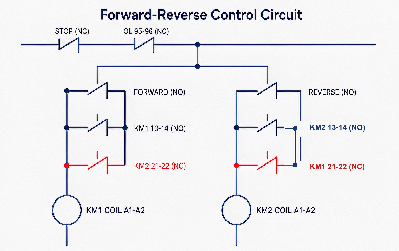
The classic hardwired forward-reverse control circuit, step by step:
Supply rail through the control fuse or breaker, then the E-stop (NC), then the overload relay’s NC trip contact (95–96) — these are common to both directions.
Forward branch: forward pushbutton (NO) in parallel with KM1’s holding contact (13–14), then — critically — through KM2’s NC auxiliary contact (21–22), then to KM1 coil (A1–A2).
Reverse branch: mirror image — reverse pushbutton / KM2 holding contact in parallel, through KM1’s NC contact (21–22), to KM2 coil.
Result: while KM1 is energized, its NC contact in the KM2 branch is open, so the reverse pushbutton does nothing until KM1 drops out. The same is true in the other direction.
Two refinements that cost one relay and prevent the worst field behavior:
Stop-first sequence: insert both direction pushbuttons behind a shared NC “stop/changeover” contact or a small timer, forcing an intentional stop between directions. This is the dead-time implementation in hardware.
Auxiliary contact count: each contactor needs one NO (hold) plus one NC (interlock) at minimum. Frames with built-in 1 NO + 1 NC cover a basic reversing starter; adding feedback or weld-detection contacts raises the count — the block options are laid out in the auxiliary contact configuration guide.
In PLC-controlled systems the cross-coupling becomes software interlock, but the hardwired NC feedback of each contactor’s actual state should still be read as an input and gated in logic — software-only interlock with no physical feedback trusts the output card more than the hardware deserves.
Mechanical Interlock: The Backstop That Works When Everything Else Fails
A mechanical interlock kit couples the two armatures so both cannot be seated simultaneously — even if a coil welds, a contact pair welds, or someone bypasses the control circuit. On the CJX2-F frames the interlock is a side-mounted bar between the two contactors; on many frames it is factory-fitted as a matched pair.
Failure scenario
Electrical interlock alone
With mechanical interlock
Control logic error (both commanded on)
Prevented — NC chain blocks the second coil
Prevented (redundant)
KM1 coil circuit faulted such that KM1 stays energized; operator presses reverse
Reverse coil blocked by KM1’s NC — but if that NC contact itself welded, nothing stops KM2
KM2 physically cannot seat; armatures bar each other
KM1 contact welded after a fault
KM2’s NC feedback is still free (coil side) — the electrical interlock does not know the main contacts are welded
Mechanical bar still blocks KM2 — partial protection, and the jam signals the fault
Wiring error during maintenance
Depends which wires were touched
Protection independent of wiring
Read the third row carefully: the mechanical interlock is the only layer that constrains a welded main contact, and even it does not make the situation safe — it turns a potential phase-to-phase explosion into a mechanical jam that the motor will stall against. That is why serious reversing installations add weld detection (next section) instead of relying on the jam.
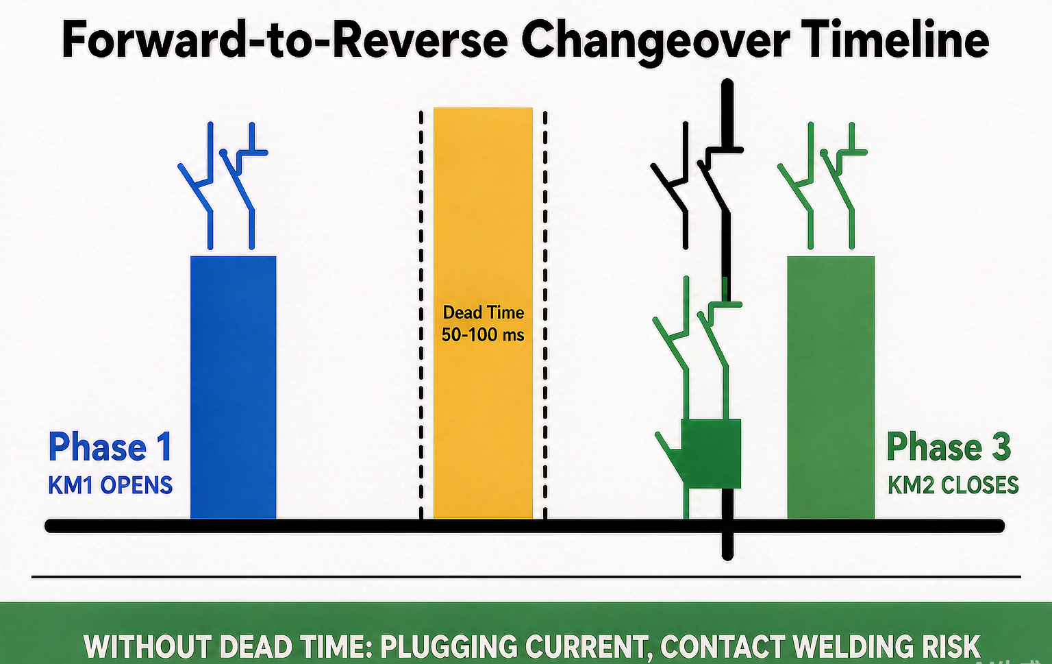
Switching Dead Time: The 50–100 ms Window
When a running motor is reversed instantly, two things happen in the transition:
The motor is still spinning near synchronous speed in the old direction. Closing the reverse contactor applies full reverse torque against a rotating rotor — “plugging” — with current at or above locked-rotor levels and torque well beyond normal starting. Every component in the path (contacts, overload, coupling, load) sees a violent event.
Reversal through AC-4 duty: plugging and inching are exactly the AC-4 utilization category; a contactor selected on its AC-3 plate will see its contact life collapse by 10–20× if the application reverses under load routinely. The category trade-offs are quantified in the AC-3 vs AC-4 comparison.
The dead-time options, in rising order of protection:
Natural two-press sequence (stop → reverse): the operator’s stop press provides the dead time; simplest and adequate for manual cranes and hoists.
On-delay timer in each branch: enforces 0.05–0.1 s between one contactor dropping and the other being permitted to pull in, regardless of operator speed.
PLC-sequenced changeover with speed or time supervision: for frequent automatic reversing (conveyor sorting, machine tools), supervising motor speed or a fixed ramp protects the mechanics as much as the contacts.
Weld Detection: What No Interlock Can Do
Both interlocks prevent the unwelded contactor from closing against a healthy one. Neither can detect that a main contact has already welded shut after a fault — and a welded KM1 pole pair across two phases is precisely the phase-to-phase short that the reverse contactor will complete if it closes.
The defense is a per-contactor “actually open” verification before enabling the opposite coil:
Voltage-sensing (auxiliary) method: a small voltage relay across each contactor’s load side confirms the motor circuit is dead (no back-EMF, no supply through a welded pole) before the reverse branch is enabled.
Mirror/positively-driven feedback method: on safety-rated contactors, the auxiliary contacts are force-guided to mirror the main contacts, so the NC feedback genuinely proves the main contact state. The standard basis is covered in the safety contactor comparison.
Weld detection matters most where reversal is frequent and currents are high (hoists, machine tools, cranes) — exactly the applications where a fault event is statistically likely over the contactor’s life.
Testing a Newly Wired Reversing Starter
Dead checks: verify phase-swap correctness at the motor terminals for both directions (rotate the motor by hand; verify tightness and torque on all lugs); confirm mechanical interlock fitted and both armatures blocked from simultaneous seating; verify overload relay setting matches motor FLC.
Control-only test (power circuit isolated): press forward — KM1 pulls in and holds; press reverse — nothing happens (interlock proven); press stop, then reverse — KM2 pulls in. Repeat in the opposite order. Any deviation means the cross-coupling is wrong before a single amp flows.
Live no-load test: jog each direction unloaded; confirm rotation direction matches the button labels (swap two motor leads if not — once, at the motor).
Load test: run loaded in both directions; clamp all three phases per direction and confirm balance; check the overload relay does not trip on the reversal events typical of the process.
Fault-injection drill (where the process justifies it): command reverse while forward is held in — verify the dead time and interlock behave. On safety-relevant installations, verify weld-detection logic with a simulated contact closure.
Common Mistakes
Mistake
Consequence
Correct practice
Reversing by swapping two motor leads instead of two contactor outputs
One direction wires through the wrong contactor path; interlock protection bypassed for that direction
Do the phase swap at the reverse contactor per the standard layout
Skipping the mechanical interlock because “the NC interlock is wired”
No defense against welded contacts or wiring errors
Fit the matched mechanical kit; verify armature blocking during dead checks
Using the contactor’s own NC for both hold and interlock via jumpers
One contact fault defeats both functions silently
Separate contacts for holding (NO 13–14) and interlock (NC 21–22)
No dead time between directions
Plugging current on every fast reversal; contact life collapse, coupling shock
Timer or stop-first sequence; AC-4-rated selection for reversing-under-load duty
Overload relay only in one contactor’s path
One direction runs unprotected
One relay on the common motor path, or matched relays in both paths
Conclusion
A safe reversing starter is three systems deep: power wiring that swaps two phases cleanly, an electrical interlock that makes simultaneous coil energization impossible in the logic, and a mechanical interlock that makes it impossible in steel. Add a deliberate dead time for the transition, and on high-duty applications add weld detection — because the failure that matters most, a welded pole pair, is invisible to both interlocks. For the basic single-contactor circuits this builds on, start with how to wire a contactor; for the starter architecture around it, see contactor for motor starter; and for the matched interlocked pair, see the CJX2-F400 mechanical interlocking contactor or browse the AC contactor category. For verifying contactor behavior in service, the measurement procedures are in the contactor testing guide.
FAQ
What is a reversing contactor interlock?
Two layers: an electrical interlock where each coil circuit passes through the other contactor’s NC auxiliary contact, so both cannot energize together; and a mechanical interlock kit that physically bars both armatures from seating at once, protecting against welded contacts and wiring errors.
Why do you swap only two phases to reverse a motor?
Reversing two of three phases flips the rotating field direction. Swapping all three leaves the rotation unchanged, and swapping at the motor instead of the contactor bypasses the interlocked switching path — do it at the reverse contactor.
What happens if both reversing contactors close at once?
Two supply phases are connected through the closed contact pairs — a phase-to-phase short circuit with fault current limited only by the supply impedance. This is the event the entire interlock chain exists to prevent.
How long should the delay be between forward and reverse?
0.05–0.1 s minimum enforced by timer or by a stop-first operating sequence. Applications that reverse under load also need the contactor selected for AC-4 duty, since plugging current approaches locked-rotor levels.
Can I use a reversing contactor on a single-phase motor?
Not by phase swapping — single-phase reversal means swapping the auxiliary/start winding polarity, which is a different circuit. Use the motor manufacturer’s reversing method; the three-phase cross-coupled scheme does not transfer.
Do I need an overload relay on both reversing contactors?
No — one overload relay on the common motor path protects both directions. If relays are fitted per-contactor instead, both paths must include them consistently, otherwise one direction runs unprotected.
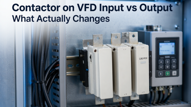
Input side sees harmonics, output side sees PWM — and neither contactor should do the drive's job. Selection margins, sequencing rules, bypass interlocking, and the DC paths where AC contactors must not go.
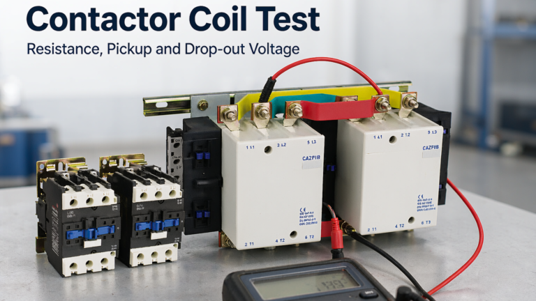
Resistance screens the winding, pickup voltage proves it will seat on a sagging bus, drop-out proves it will release. Reference bands, IEC windows, and the five root causes behind burnt coils.
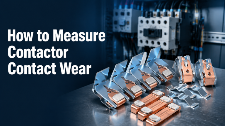
Four measurable wear indicators with instruments, thresholds and baselines: 4-wire micro-ohm resistance, tip thickness, overtravel, and IR temperature rise — and the judgment line between new tips and a new contactor.