Types of Modular Contactors: A Practical Selection Guide
Types of modular contactors explained: poles, AC-7a vs AC-7b duty, NO vs NC contact forms, latching types and coil options, with an application-to-type selection matrix.
Read More
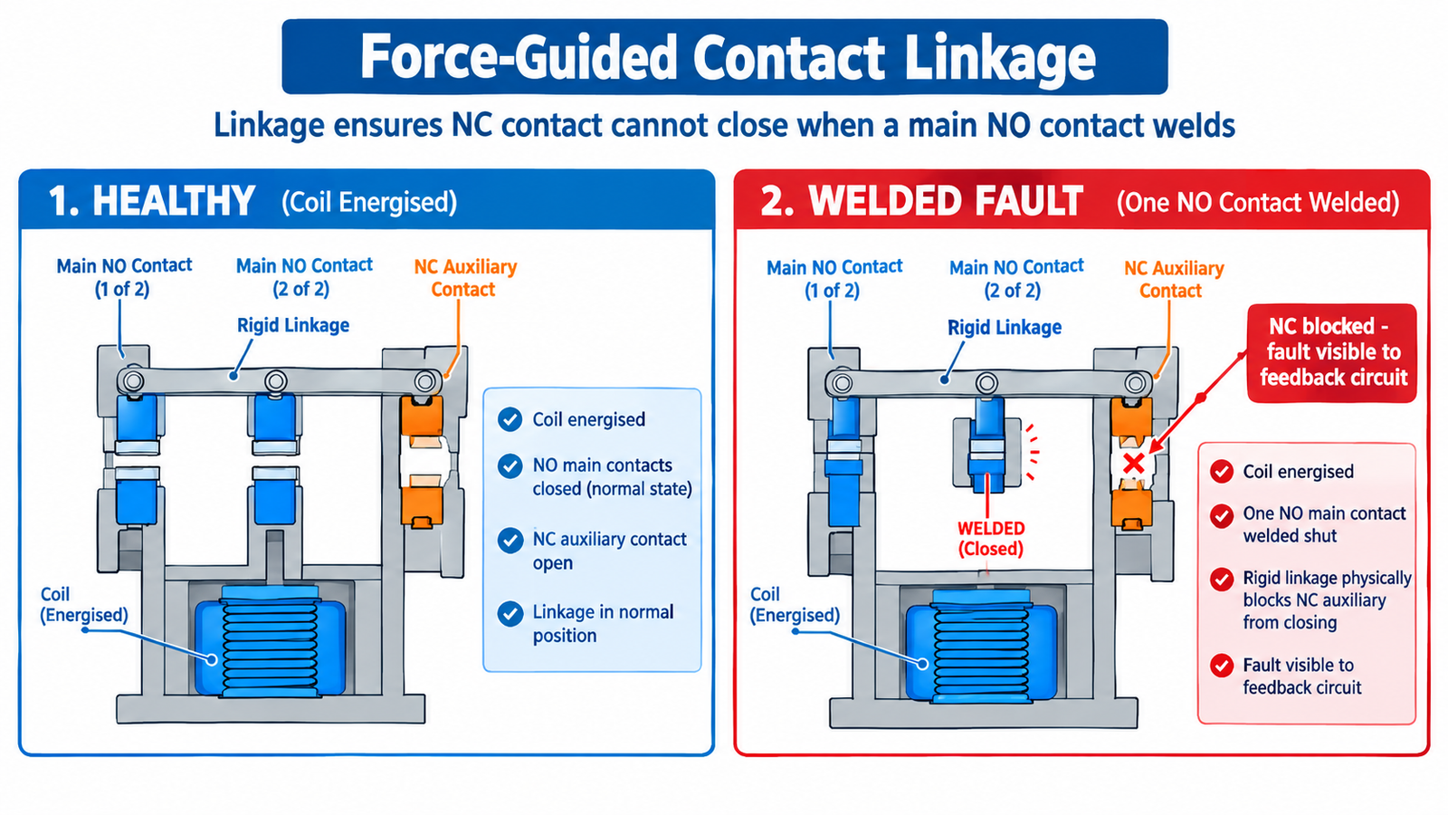
The difference between a safety contactor vs standard contactor is not current rating, coil voltage or brand tier — it is what happens mechanically when a contact welds. A standard contactor’s auxiliary contacts move independently of its main contacts, so a welded main contact can leave the control system reading “safe” while the motor stays energised. A safety contactor uses force-guided contacts: a rigid mechanical linkage that makes a false “safe” reading physically impossible. That one design difference decides which devices are permitted in emergency-stop and guard circuits, and which are not. This guide explains force-guided and mirror contact mechanics, shows how feedback monitoring actually works, and maps out when a standard AC contactor may still be used.
| Aspect | Standard contactor | Safety contactor |
|---|---|---|
| Contact linkage | Main and auxiliary contacts move independently | All contact sets mechanically linked (force-guided) |
| Welded main contact behaviour | NC auxiliary may still close — false “safe” signal possible | Linkage physically blocks NC from closing — fault is visible |
| Governing feature standards | IEC 60947-4-1 basic performance | IEC 60947-4-1 Annex F (mirror contact) and/or IEC 60947-5-1 Annex L (positively driven) |
| Feedback monitoring | Only meaningful if a mirror contact is declared | Designed for it; usually mandatory in the architecture |
| Usable up to | Category B/1, low risk (if risk assessment allows) | Category 3/4, PL d/e in redundant configurations |
| Typical duty | Motor starting, heating, lighting, general switching | E-stop, guard interlock, safe-off of drives |
Inside a safety contactor, every contact set — main poles and auxiliary contacts alike — sits on a common, rigidly linked actuating system. The linkage enforces one rule: normally open and normally closed contacts can never change state in contradictory ways. If any normally open contact welds shut, the linkage physically prevents the normally closed contacts from closing. The control system that reads those NC contacts therefore gets a truthful answer: “something is stuck, do not re-energise.”
A standard contactor makes no such promise. Its auxiliary contact block is a clip-on accessory driven by the same armature during normal operation, but nothing guarantees its behaviour when a main contact fuses. During normal duty that independence is harmless — which is why the two products coexist. In a safety function, the difference is the difference between a detectable fault and a silent one.
The failure this guards against is not exotic. Contact welding is the classic end-of-life mode for a contactor that has switched a stalled motor, closed onto a short circuit, or simply reached its electrical endurance. The troubleshooting guide lists the symptoms; the point here is that on a standard contactor the welded state is invisible to the control circuit.
Terminology gets muddled here, and the distinction matters when you read a datasheet.
One device can satisfy both, and many do. The practical consequence: a standard power contactor with a declared mirror contact already supports reliable feedback monitoring, and some standard families include it without being marketed as safety products. A contactor with fully positively driven contacts goes further and is the device you specify when the risk assessment lands in Category 3/4 territory. Always read the specific datasheet — the feature is declared per family and frame, never inferred from the series name. The distinction between the two contact types themselves is explored further in the auxiliary vs main contact guide.
The mechanical linkage is only half the system. The other half is the feedback loop that turns contact state into information the safety function can act on.
The NC auxiliary (mirror) contact of each contactor is wired in series with the others and returned to the feedback input of a safety relay or safety PLC. When the safety function de-energises the contactors, the evaluation unit expects the NC chain to close — proving every contactor actually dropped out. If any contactor has a welded contact, its NC stays open, the chain never completes, and the system blocks restart until the fault is cleared. Wired this way, the diagnostic coverage of the reaction subsystem can reach the highest band, because the dangerous failure is detected at the latest on the next demand.
Two monitoring styles exist. Static feedback monitoring checks the off-state before re-energising — simple, and sufficient for high coverage in most machinery. Dynamic monitoring additionally pulses or continuously interrogates the chain, which also catches wiring faults such as a bridged feedback loop. If you are wiring the loop yourself, the same discipline applies as in any contactor control circuit — see the contactor wiring guide — with the added rule that feedback contacts must be dedicated to the safety function and never paralleled with other duties.
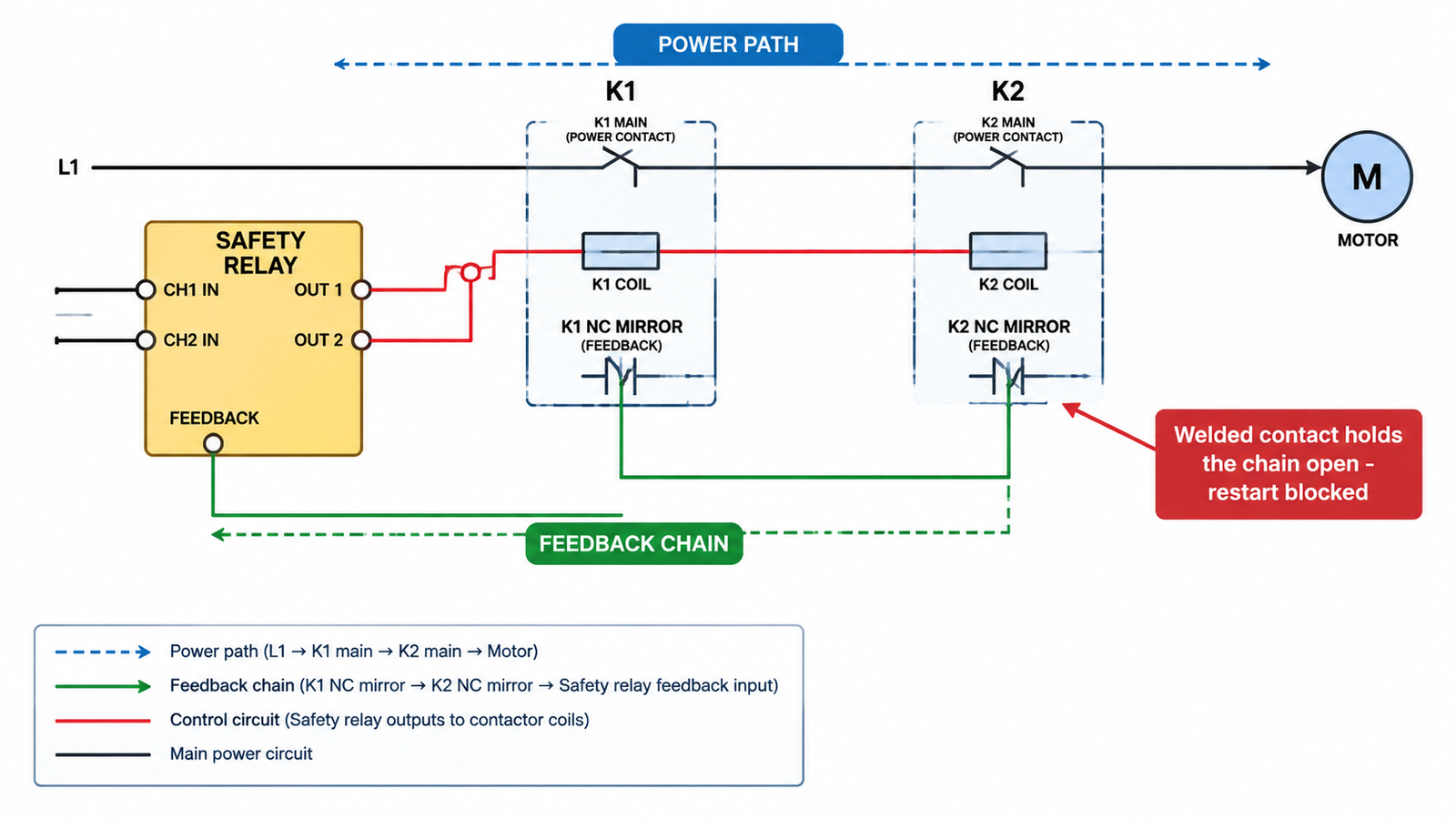
For lower-risk functions, a single safety contactor with monitored feedback is a legitimate architecture. For higher risk, two contactors are wired so their main contacts are in series in the power path, each with its own mirror contact in the feedback chain, and the safety relay monitors both. Single-fault tolerance then holds: if one contactor welds, the other still breaks the circuit, and the feedback chain reports which device failed. This is the standard route to Category 3/4 and PL d/e under EN ISO 13849-1. The exact achievable Performance Level also depends on component reliability data and demand frequency, so the configuration must be validated with the manufacturer’s safety data rather than assumed.
EN ISO 13849-1 does not ban standard components; it grades them. Where the risk assessment produces a low Performance Level requirement, a standard contactor can be used — with conditions that are often overlooked.
| Situation | Acceptable device | Condition |
|---|---|---|
| No safety function at all — motor start/stop, heating, lighting | Standard contactor | Normal control requirements only |
| Low-risk safety function, Category B/1 (PL a/b) | Standard contactor | Documented risk assessment; reliability assumptions must be justified |
| Category 2 / PL c with monitored release | Standard contactor with declared mirror contact preferred | Feedback monitoring required from Category 2 up |
| Category 3 / PL d | Safety contactor, redundant pair with feedback | Positively driven or mirror contact declared per datasheet |
| Category 4 / PL e | Safety contactors, redundant, monitored, validated | Full single-fault tolerance; verified with reliability data |
Two clarifications prevent most mistakes. First, “safety contactor” is an application-and-declaration status, not just a colour scheme: what qualifies the device is the declared contact behaviour and the manufacturer’s safety data, which feeds your ISO 13849-1 calculation. Second, using a standard contactor above its justified category is not a corner case to be weighed — it is a nonconformity that surfaces in machine audits and, worse, in incident investigations. Internal component quality still matters for endurance and consistency; the anatomy behind it is covered in the contactor construction guide.
For general-purpose motor duty, frame selection follows the ordinary rules; for instance, compact frames in the CJX2-D (LC1-D) series cover the small and mid-range motor spectrum where most non-safety switching lives — the safety variant decision applies only to the contacts declared for the safety function.
| Mistake | Why it matters |
|---|---|
| Assuming any NC auxiliary contact works as feedback | Without a mirror contact declaration, the NC can close while a main contact is welded — the false-safe condition the loop exists to catch. |
| Paralleling feedback contacts with other duties | The chain must be dedicated; shared contacts introduce faults the monitoring cannot interpret. |
| Buying “red” hardware without safety data | Colour is not certification; the ISO 13849-1 calculation needs B10d/MTTFd for the specific frame. |
| Using one contactor where the risk assessment needs redundancy | Category 3/4 requires single-fault tolerance, which a single device cannot provide. |
| Skipping the mirror-contact check on standard contactors | Many standard families include Annex F contacts — usable in monitored architectures — but only the datasheet confirms it. |
A safety contactor is defined by one mechanical promise: its contacts cannot lie about the machine’s state. Force-guided linkage and mirror contacts turn a welded contact from a silent hazard into a detectable, blockable fault, and feedback monitoring converts that detection into a restart block. Standard contactors remain the right choice everywhere the risk assessment allows — which is most of the panel. The engineering task is to know which circuits are which, and to specify contact behaviour, not colour, at the point of purchase.
A contact set in which normally open and normally closed contacts are connected by rigid mechanical linkage so they can never be closed at the same time. If any NO contact welds shut, the linkage physically prevents the NC contacts from closing, exposing the fault to the feedback circuit.
A mirror contact (IEC 60947-4-1 Annex F) is an auxiliary NC contact on a power contactor guaranteed not to close while any main contact is closed. Force-guided or positively driven contacts (IEC 60947-5-1 Annex L) apply the mechanical linkage across a whole set of NO and NC contacts with a guaranteed separation. One device can satisfy both requirements.
Only where the risk assessment justifies a low Performance Level (Category B/1), and preferably with a declared mirror contact so the state can be monitored. For Category 3/4 requirements, redundant safety contactors with monitored feedback are required.
The NC mirror contacts of all contactors are wired in series back to the safety relay. After de-energising, the relay expects the chain to close. A welded main contact holds its NC open, the chain stays broken, and the relay blocks restart until the fault is removed.
Category 4 / PL e architectures require single-fault tolerance, which in contactor-based circuits is achieved with two contactors in series, each monitored through its own mirror contact, evaluated by a safety relay or safety PLC with validated reliability data.
No. Oversizing adds endurance, not truthful state reporting. Whether a device is usable in a safety function depends on its declared contact behaviour and published safety data, not on its current rating.