Types of Modular Contactors: A Practical Selection Guide
Types of modular contactors explained: poles, AC-7a vs AC-7b duty, NO vs NC contact forms, latching types and coil options, with an application-to-type selection matrix.
Read More
A NEMA Class 20 vs IEC Class 10 overload relay comparison confuses buyers because the two standards have adopted different default trip classes — and because the class number is often misread as a quality grade. It is not. The class is a timing envelope measured in seconds at a defined overcurrent, and every class exists for a specific starting duty. NEMA-style relays happen to ship as Class 20 because of how North American starters are sized; IEC relays happen to default to Class 10 because IEC practice sizes each relay precisely to the motor. Neither default is better. What matters is matching the class to the motor’s safe stall time. This guide decodes the trip class system, shows the actual test points behind it, and explains how to specify the right class on either framework — including on heavy frames such as an AC contactor starter assembly.
IEC 60947-4-1 defines trip class as the maximum time a cold relay may take to trip when carrying 7.2 times its set current. NEMA documents express the same test point as 600% of full-load current — the shorthand differs slightly, the physics does not. The standard classes are 10A, 10, 20 and 30, meaning 10, 20 or 30 seconds at that test current.
The class number only governs behaviour in the high-overcurrent region. At the other end of the curve, a correctly set relay must not trip at 1.05 times setting, must trip within two hours at 1.2 times setting, and must not trip within two minutes at 1.5 times setting. Those points exist so the relay rides through starting current and normal service-factor operation while still catching a genuine overload.
| Test condition (cold relay) | Required behaviour |
|---|---|
| 1.05 × set current | No trip within 2 hours |
| 1.2 × set current | Trip within 2 hours |
| 1.5 × set current | No trip within 2 minutes |
| 7.2 × set current (≈600% FLA) | Trip within the class time: 10A/10/20/30 seconds |
For application work the useful figure is the practical envelope, not the single test point. Manufacturers publish trip-time bands because the bimetal or electronic model does not trip instantly at the class boundary.
| Class | Typical trip envelope at 7.2 × Iset | Standard origin |
|---|---|---|
| Class 10A | 2–10 s | IEC sub-grade, faster floor |
| Class 10 | 4–10 s | IEC default for normal-duty motors |
| Class 20 | 6–20 s | NEMA default; IEC option for high inertia |
| Class 30 | 9–30 s | Very long acceleration duty |
NEMA starters are sized by standardized frame — Size 0, Size 1, Size 2 — each covering a horsepower band with generous margins. Because the same relay may serve several motor sizes and because North American designs tolerate service-factor running, the conservative Class 20 became the default. The heater-element system is also partly responsible: NEMA practice swaps heaters rather than dialling a wide adjustment range, so a slower class keeps the selection forgiving.
IEC practice does the opposite. The relay is chosen so its adjustment window brackets one motor’s nameplate current, with the set point near the middle of the dial. Precise sizing makes a fast Class 10 response safe: the relay is not going to see legitimate current above setting during normal running, so there is no need for a wide timing margin. The bimetallic working principle behind those curves is identical in both camps — the frameworks differ in sizing philosophy, not in the sensing element.
So when a quotation sheet says “Class 20” next to a NEMA device and “Class 10” next to an IEC device, you are looking at two answers to two different sizing questions, not two levels of protection quality.
This is the most damaging misreading of the specification. A longer trip window protects better only when the motor’s safe stall time is longer than the class window. When it is not, the extra seconds are exactly the window in which the rotor bakes.
The rule works in both directions:
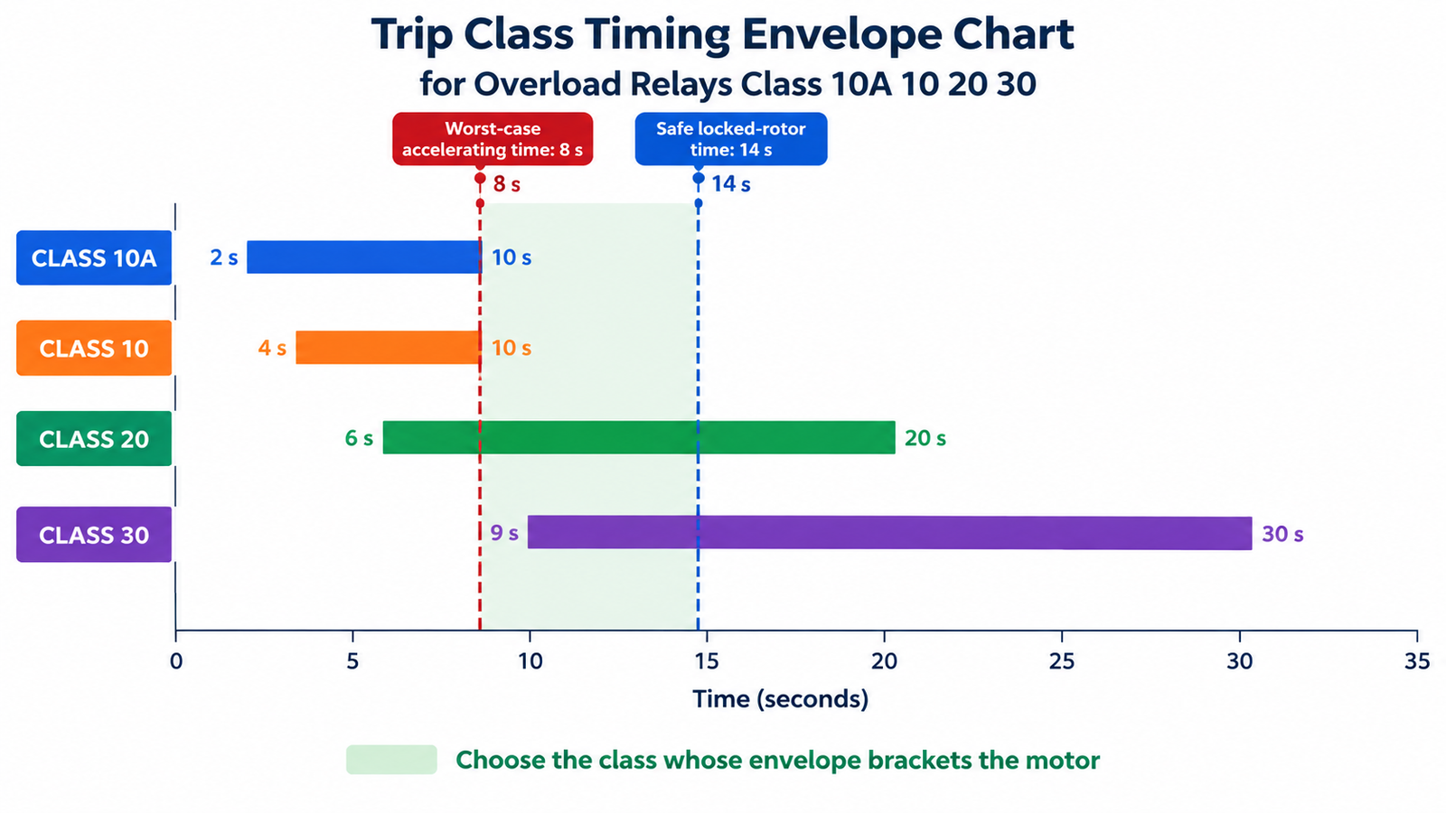
Because both conditions must hold simultaneously, the correct class is the one whose envelope brackets the motor: lower bound below stall withstand, upper bound above accelerating time. Where the motor sits between classes, the accelerating time is reduced (soft start, unloaded start) or a faster-protecting class with a higher set point is chosen deliberately. For the starter-level view of this trade-off, see the guide to contactors in motor starter applications.
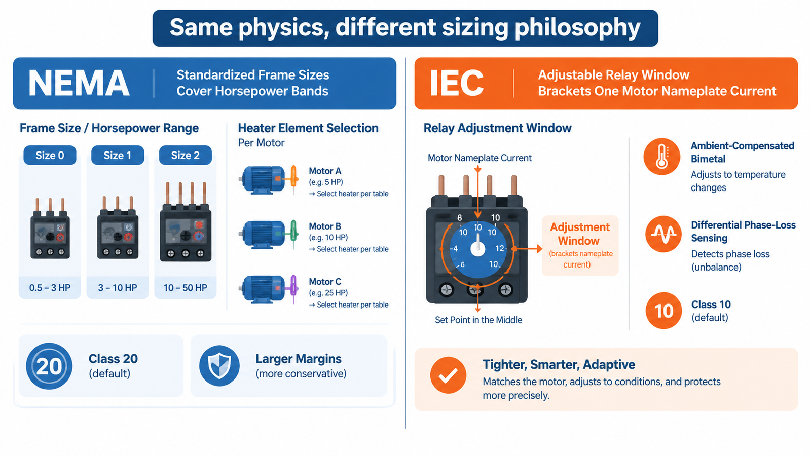
If the class number itself is not the dividing line, what actually differs between the two families? Three practical behaviours do.
Most IEC thermal relays are ambient-compensated: a compensating bimetal cancels the effect of panel temperature so the trip point follows motor current, not cabinet weather. Many NEMA heater-type relays carry no such compensation, so a hot panel shifts the effective trip point downward and a cold morning shifts it upward. In a wash-down plant room at 45 °C, compensation is worth more than any class choice.
IEC relays commonly use differential sensing — the three bimetals are linked so that unequal heating (the signature of a lost phase, where two phases overheat while the third stays cold) trips the relay early. Basic NEMA heater relays respond to average heating and may tolerate a single-phased motor for a surprisingly long time. Differential models exist in both worlds, but the feature is near-universal in IEC practice and optional elsewhere. The mechanism is covered in the overload relay contact guide.
IEC relays use narrow, continuous adjustment ranges, which makes one relay model family cover many motors — good for spare-parts inventory. NEMA heaters are selected per motor, which makes field swaps simpler in a standardised plant. Neither approach is wrong; they optimise for different maintenance models.
Take a 200 kW, 400 V conveyor that must reverse under load, driven through a mechanically interlocked pair of 400 A AC-3 contactors such as the CJX2-F400 interlocking set. Reversing duty puts the contactors through plugging-like current transitions, which is the AC-4 end of the duty spectrum described in the AC-3 vs AC-4 comparison — and it also stresses the overload relay’s thermal image, because reversal restarts the heating cycle from a warm state.
The conveyor accelerates in about 8 seconds when loaded. Motor safe stall time at locked-rotor current is 14 seconds. The correct relay is therefore Class 20: its 6–20 s envelope sits fully inside the stall limit at the lower end and above the 8-second acceleration at the upper end. Specifying the IEC-default Class 10 here would trip the drive on every loaded start; specifying “Class 20 because NEMA” without checking the 14-second stall figure would have been luck rather than engineering.
On a 400 A frame, the same logic applies to the short-circuit coordination: the relay class says nothing about fault duty. That is governed by the coordination table of the SCPD, as covered in the general-purpose starter discussion.
To make a procurement specification unambiguous regardless of which standard the supplier works in, write it functionally:
A supplier working to NEMA conventions can meet this with a Class 20 device plus the right heater; an IEC supplier can meet it with the appropriate adjustable relay. The specification no longer depends on which convention the catalogue happens to use. Deeper selection factors — heating type, reset mode, phase-loss sensing — are covered in the overload relay selection guide.
| Mistake | What actually happens |
|---|---|
| Treating Class 20 as “more protection” | On short-stall motors the relay permits stall heating well past the damage curve. |
| Defaulting everything to Class 10 “because IEC” | High-inertia starts nuisance-trip; operators eventually disable protection. |
| Comparing a NEMA 600% figure with an IEC 7.2× figure as if they conflicted | They are the same test point in different notation; the comparison wastes a specification cycle. |
| Ignoring ambient compensation on a hot panel | Trip points drift with season; protection gaps open exactly when thermal stress peaks. |
| Choosing class without the motor’s safe stall time | The class is selected by habit, and both nuisance trips and silent under-protection follow. |
NEMA Class 20 and IEC Class 10 are defaults born of two sizing philosophies, not two grades of protection. Read the class as a timing envelope, anchor it to the motor’s accelerating time and safe stall time, and the standard debate disappears — the right class is whichever one brackets your motor. Specify it that way and the same motor is equally well protected by either framework’s hardware.
The difference is the trip timing envelope at high overcurrent: Class 20 allows up to 20 seconds at roughly 600% of setting, Class 10 allows up to 10 seconds. NEMA starters default to Class 20 because frames are sized by horsepower band; IEC relays default to Class 10 because each relay is sized precisely to the motor. Neither is inherently better — the class must match the application.
Only if the motor’s safe stall time exceeds 20 seconds. For a motor that withstands locked-rotor heating for 10 seconds, Class 20 is less safe, because it keeps current flowing past the thermal damage point during a true stall.
Class 10A is a tighter IEC sub-grade of Class 10: it must trip within 2–10 seconds at 7.2 times setting, where plain Class 10 allows 4–10 seconds. It trades a little starting margin for faster thermal protection.
Yes. Class 20 and Class 30 relays are widely available in IEC ranges and are the standard answer for high-inertia loads such as large fans, mixers and loaded conveyors.
They describe the same test condition with different notation: 600% of full-load current is NEMA shorthand, 7.2 times set current is the IEC test point. The numbers coincide closely because locked-rotor current typically sits near six to seven times full-load current.
Measure or calculate worst-case accelerating time, obtain the motor’s safe locked-rotor time, and select the class whose envelope (Class 10: 4–10 s, Class 20: 6–20 s, Class 30: 9–30 s) sits between the two. If no class fits, change the starting method rather than the class.