To test an AC contactor, check three things with a digital multimeter: the coil, the main contacts, and the mechanical pull-in. A coil that reads open circuit, contacts that stay closed when de-energized, or a unit that fails to click when powered are all signs of a bad contactor. This guide walks through each test in order, gives you the readings to look for, and tells you when to repair versus replace.
What You Are Checking and Why
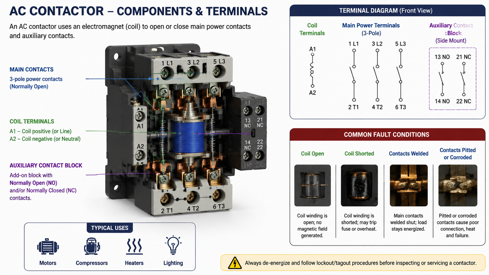
An AC contactor is an electrically operated switch: a coil pulls a set of contacts together to feed power to a motor, compressor, heater, or lighting load. When it fails, the symptoms usually come from one of three parts. The coil may be open or shorted so the contactor cannot pull in. The main contacts may be welded shut, pitted, or corroded so power is either always on or intermittently interrupted. Or the mechanical mechanism may be stuck so the armature cannot move freely.
The fastest way to find the failing part is a resistance test with the power off, followed by a live voltage or drop test. You do not need a bench or an expensive tester; a standard multimeter covers every check in this guide.
Safety First
Contactors sit in the power path, so the first step is always to de-energize the circuit. Turn off the breaker or disconnect that feeds the contactor and follow any lockout/tagout procedure required at your facility. For a residential air conditioner, switch off the outdoor unit’s disconnect and the breaker at the panel.
Confirm the power is actually off before touching any terminal. Set the multimeter to AC volts and check between the line terminals (usually marked L1, L2, and L3 on a three-pole unit) and between each line terminal and ground. Read 0 V AC before you open the panel or remove wiring. Capacitors near the contactor can hold a dangerous charge, so treat anything inside the control enclosure as live until you verify it.
Tools You Need
Digital multimeter with resistance (ohms) and continuity modes, plus AC and DC voltage ranges
Insulated screwdrivers and a small flat-blade tool for terminal screws
Safety glasses and electrically rated gloves where facility rules require them
A camera or phone to photograph the wiring before you disconnect anything
Step 1: Inspect Visually First
A surprising number of contactor faults are visible before you pick up the meter. Look at the contacts through the arc chamber openings or with the cover removed. Blackened or pitted contact surfaces, melted plastic, or a coil with a burnt or swollen appearance all point to a failed part. Check that the terminal screws are tight; a loose connection produces heat and intermittent operation that looks like a contactor fault. A rusty or discolored coil is worth testing even if the contactor still clicks, because a degraded winding can fail under load.
Step 2: Test the Coil
The coil is the part that pulls the contactor in. Test it with the contactor removed from the circuit or with the coil terminals isolated.
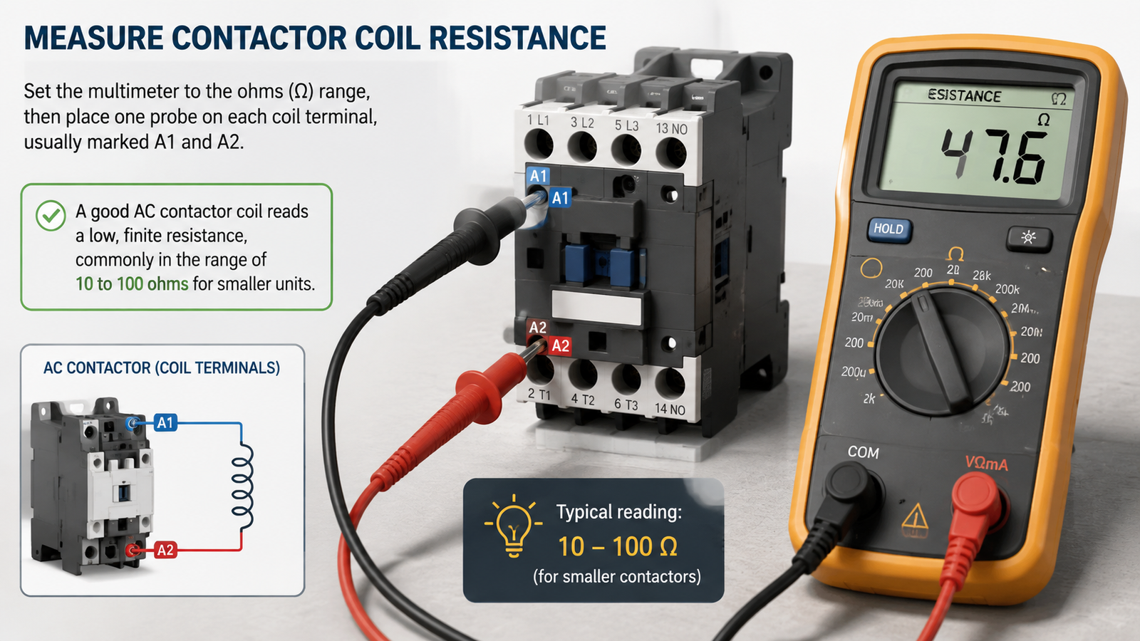
Set the multimeter to the ohms range, then place one probe on each coil terminal, usually marked A1 and A2. A good AC contactor coil reads a low, finite resistance, commonly in the range of 10 to 100 ohms for smaller units. A reading of “OL” or infinity means the winding is open and the coil must be replaced. A reading very close to zero can mean a shorted winding. Compare the measured value against the manufacturer’s datasheet or a known-good unit when one is available, because the exact figure depends on coil voltage and contactor size.
Step 3: Test the Main Contacts
The main contacts are the power-carrying pairs between the line and load terminals, such as L1 to T1, L2 to T2, and L3 to T3 on a three-pole contactor. With the coil de-energized, the contacts should be open, so the meter should read “OL” or no continuity between each line and load pair.
To test whether the contacts close properly, you have two options. Manually press the armature in with an insulated tool, or apply the rated coil voltage briefly, then measure continuity across each contact pair. A closed contact should read near 0 ohms, typically well under 1 ohm. A reading of a few ohms or higher indicates pitted, worn, or contaminated contacts that will overheat under load. If the contactor reads continuity while it is de-energized, the contacts are welded or stuck closed, and the unit must be replaced.
Step 4: Test Auxiliary Contacts
Auxiliary contacts are the small contacts used in the control circuit for interlocks, indication, or seal-in wiring. They come in two types. Normally open (NO) contacts are open at rest and close when the contactor pulls in. Normally closed (NC) contacts do the opposite: they are closed at rest and open when energized.
Test each pair the same way you tested the main contacts. With the coil de-energized, an NO contact should read open and an NC contact should read closed. When you press the armature in or energize the coil, the states should reverse. If an NC auxiliary stays open at rest or an NO contact fails to close, the contact block is worn and should be replaced.
Step 5: Energize the Coil and Confirm Operation
A resistance test tells you the coil is intact, but it does not prove the contactor will pull in under its control voltage. Reconnect the coil wiring, restore power to the control circuit only, and listen. A healthy contactor clicks firmly when the coil is energized and releases with a second click when power is removed. A soft buzz or chatter instead of a clean click usually means low coil voltage, a dirty or worn magnet face, or a failing shading ring.
Measure the coil voltage at the A1 and A2 terminals while the contactor should be energized. It should match the coil rating on the nameplate, such as 24 V AC, 110 V AC, or 220 V AC, within roughly 85 to 110 percent. If the coil voltage is correct but the contactor will not pull in, the problem is the mechanism or the coil itself. If the voltage is missing or far below rating, trace the control circuit, thermostat, or relay feeding the coil.
Step 6: Check Voltage Drop Under Load
The final check confirms that the closed contacts can carry current without excess resistance. With the system running under a normal load, place the meter in AC volts and measure across each closed contact pair, line to load. A good contact shows a very small voltage drop, usually well under 1 V. A larger drop means the contacts are worn or contaminated and are dissipating power as heat, which will eventually damage the contactor and the connected equipment. Compare the reading across all poles; one pole with a noticeably higher drop is usually the worn one.
Interpreting Your Readings
Test
Good reading
Fault reading
Action
Coil resistance (A1–A2)
Low finite ohms, typically 10–100 Ω
“OL”/open, or near 0 Ω
Replace coil or contactor
Main contacts de-energized
Open, no continuity
Continuity (welded/stuck)
Replace contactor
Main contacts energized
Near 0 Ω
Several ohms or unstable
Replace contacts/unit
Voltage drop under load
Well under 1 V AC
1 V or more
Replace contacts/unit
Coil voltage at A1–A2
Matches nameplate rating
Missing or far below rating
Repair control circuit
When to Replace Instead of Repair
Replace the contactor when the coil is open or shorted, the main contacts are welded or badly pitted, or the plastic body shows heat damage. These failures are not reliably repairable in the field, and a patched contactor is a recurring failure point on a motor or compressor circuit. If the coil and contacts both test fine but the unit buzzes or sticks, a clean of the magnet faces or replacement of a worn contact block may be enough. In all cases, fit the same coil voltage, pole count, and current rating as the original, and confirm the utilization category matches the load.
There is no single value for every unit. Small contactors commonly read in the 10 to 100 ohm range, but the correct figure depends on coil voltage and contactor size, so compare against the datasheet or a known-good unit. The decisive checks are whether the coil reads open (OL), which means a broken winding, or near zero, which suggests a short.
Can I test a contactor with a continuity tester?
Yes. Use the continuity mode to confirm that the main and auxiliary contacts open and close correctly with the coil off and on. Continuity mode works well for the contacts, but a resistance reading is more useful for the coil because it lets you spot a partial short rather than just an open circuit.
Why does my contactor buzz but not pull in?
Buzzing without a solid click usually comes from low coil voltage, a dirty or worn magnet face, a failing shading ring, or a mechanically stuck armature. Check the coil voltage first, then inspect the magnet faces and the moving parts before deciding whether to replace the unit.
Should I replace a contactor with a burnt or pitted contact?
Generally yes. Pitting and burning raise contact resistance, which produces heat and intermittent operation. Unless the damage is light surface contamination that can be cleaned safely, replace the contactor rather than risk a recurring fault on a motor or compressor circuit.
Conclusion
Testing an AC contactor comes down to three measurements: coil resistance, contact continuity, and operating voltage. A meter plus a careful look at the contact surfaces is usually enough to tell you whether the coil is open, the contacts are welded or worn, or the control circuit is starving the coil of voltage. Fix the wiring when the coil never gets its rated supply; replace the contactor when the coil or contacts themselves have failed.
If you are sourcing a replacement AC contactor, contact the Wilmall team with your coil voltage, current rating, and pole count, and we will help you match the correct unit for your motor or compressor circuit.
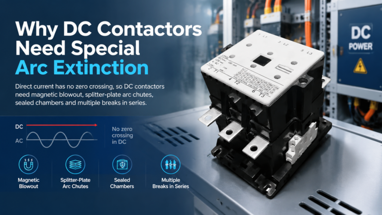
DC contactors need special arc extinction because DC current has no natural zero crossing. See how magnetic blowout, arc chutes and series breaks kill a DC arc — and how to specify one correctly.
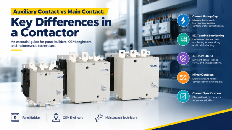
Main contacts carry the motor current; auxiliary contacts carry control signals. Learn the real rating gap, IEC terminal codes, and how to spec both correctly.
A sourcing guide to modular contactor manufacturers: match the four supplier archetypes, qualify any factory with a nine-point framework, and send an RFQ that gets comparable quotations.