Auxiliary Contact vs Main Power Contact Key Differences in a Contactor
Main contacts carry the motor current; auxiliary contacts carry control signals. Learn the real rating gap, IEC terminal codes, and how to spec both correctly.
Read More
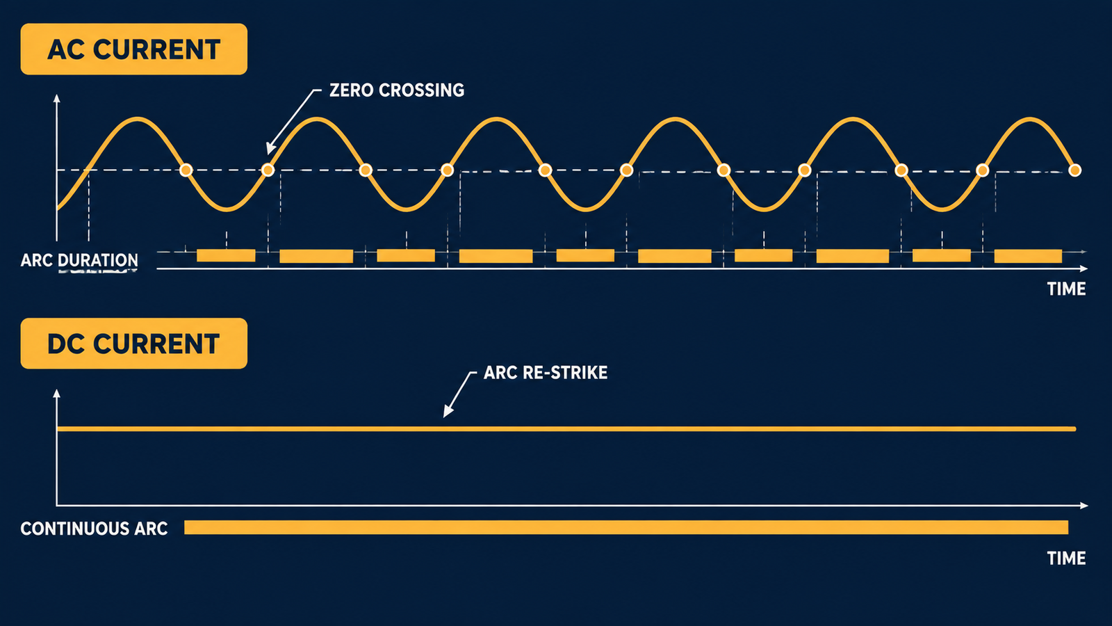
Break a loaded circuit and an arc will form — that is true for every contactor, whether it switches alternating or direct current. The difference is that an AC contactor gets help from physics: the current crosses zero 100 or 120 times every second, and the arc dies at the next crossing. A DC contactor gets no such help. Direct current never crosses zero, so the arc keeps burning until the device actively forces it out. That single difference is why DC switching demands special arc-extinction design — magnetic blowout, splitter-plate arc chutes, sealed chambers, and multiple breaks wired in series — and why a contactor selected for an AC panel cannot simply be reused on a DC circuit.
This guide explains the physics behind DC arc extinction, the four mechanisms engineers use to kill a DC arc, the energy and time-constant rules that decide how hard the break will be, and the specification checks that prevent the most expensive mistakes in solar, battery, traction, and DC control-panel projects.
DC contactors need special arc-extinction design because DC current has no natural zero crossing. An AC arc collapses on its own at every zero crossing; a DC arc burns continuously as long as the source can sustain it. To extinguish a DC arc, the contactor must raise the voltage drop across the arc above the supply voltage — and hold it there long enough for the energy stored in the circuit inductance to dissipate. It does this with magnetic blowout that drags the arc off the contacts, splitter-plate chutes that chop the arc into a series of short high-voltage gaps, sealed gas-filled or vacuum chambers that cool and de-ionize the plasma, and multiple contact breaks connected in series. A real DC contactor is not an AC contactor with a DC coil — it is a mechanically different device.
| Switching aspect | AC contactor | DC contactor |
|---|---|---|
| Natural current zero | 100–120 per second | None — current never reverses |
| Extinction mechanism | Arc dies at the next zero crossing; chute cools and prevents re-strike | Arc must be forced out by raising arc voltage above the source voltage |
| Typical hardware | Compact de-ion chute, no blowout magnets | Permanent magnets or blowout coils, deep chutes, larger contact gaps |
| Key rating inputs | Voltage, current, utilization category, cos φ | Voltage, current, utilization category, and L/R time constant and polarity |
| Wrong-device failure | Chatter, coil burnout, contact erosion | Welded contacts at break, chute erosion, arc flash |
An arc is a column of ionized, conductive plasma. When contacts separate under load, the metal bridge vaporizes and the gap becomes a conducting path, so current keeps flowing through the air. In an AC circuit this state cannot last: twice per cycle the current passes through zero, the energy feeding the arc momentarily disappears, and the only question is whether the gap recovers its dielectric strength faster than the recovery voltage can re-strike the arc. The contactor’s arc chute does that cooling job in a few milliseconds, and the waveform does the rest.
In a DC circuit the current never reverses and never reaches zero. The source keeps pushing the same current through the plasma for as long as the arc can conduct it. If nothing intervenes, the arc burns until something fails: the contacts erode away, the surrounding insulation carbonizes, or the molten contact pools freeze into a solid weld. A DC arc also transfers contact material in one direction only — from anode to cathode — building a pip on one contact and a crater on the other, which eventually interlocks the contacts like a mechanical latch.
Extinction is not just a voltage problem — it is an energy problem. When a contactor opens an inductive DC circuit, two energy sources feed the arc: the supply, which keeps pushing current through the gap, and the circuit inductance, which releases everything it stored while current was flowing. That stored energy is ½ × L × I², and the arc must absorb every joule of it before the current can fall to zero.
The numbers scale fast. Take a 220 V DC distribution circuit breaking 100 A with an L/R time constant of 2 ms: the loop resistance is 2.2 Ω, the inductance is 4.4 mH, and the stored energy is about 22 joules. Raise the time constant to 7.5 ms — typical for a series-wound DC motor — and the same 100 A break must absorb more than 80 joules, roughly four times as much, inside the same few milliseconds. This is why two contactors with identical voltage and current ratings can behave completely differently on different loads: the inductance decides how much punishment the arc chamber takes.
Because inductance dominates the difficulty, IEC 60947-4-1 defines DC utilization categories by the circuit’s time constant — the ratio of inductance L to resistance L/R, expressed in milliseconds. The larger the time constant, the longer the arc burns and the harder the break:
| Category | Load type | Time constant (L/R) | Breaking duty |
|---|---|---|---|
| DC-1 | Non-inductive or slightly inductive loads, resistance furnaces, heaters | ≤ 1 ms | Light — arc energy mostly from the supply |
| DC-3 | Shunt-wound DC motors: starting, plugging, inching, dynamic braking | ≤ 2 ms | Difficult — make ≈2.5× rated current, break at up to full supply voltage |
| DC-5 | Series-wound DC motors: starting, plugging, inching, dynamic braking | ≤ 7.5 ms | Severe — highest arc energy, break voltage can equal line voltage |
The same logic applies on the auxiliary side: switching a contactor coil or solenoid on a DC control circuit is a DC-13 duty, and the small-looking coil can still deliver a sharp inductive kick. If you are mapping AC-side duties to compare, the AC-1 to AC-4 utilization categories follow the same IEC 60947-4-1 logic.
Since the arc will not die on its own, DC contactor design concentrates on one goal: raise the arc voltage above the source voltage, then keep it there while the gap cools. Production designs combine four mechanisms.
A current-carrying arc sitting in a magnetic field feels a sideways Lorentz force — F = B × I × L. DC contactors exploit this with either permanent magnets mounted beside the contact gap or a series-connected blowout coil that generates a field proportional to the load current. When the contacts part, the field drives the arc rapidly sideways, stretching it and dragging its roots off the contact faces. The characteristic sharp “snap” of a large DC contactor opening is the sound of the arc being slammed into the chute.
Blowout has one DC-specific consequence buyers often miss: polarity. The magnetic field has a fixed direction, so the Lorentz force flips if the load current is connected in reverse — instead of pushing the arc into the chute, the contactor blows the arc back onto the contacts and mounting structure. Polarized DC contactors carry terminal polarity markings, and manufacturers such as ABB explicitly require the marked polarity to be respected on their permanent-magnet DC designs. Always check the terminal markings before wiring.
Once the blowout field pushes the arc into the chute, a stack of ferromagnetic splitter plates divides it. Each pair of plates captures one arc root, and because every root needs roughly 20–30 V to sustain itself in air, the plate stack converts one long arc into a series of short arcs whose voltages add up. A chute with 15 active gaps produces on the order of 300–450 V of total arc voltage — comfortably above a 220 V supply, which is exactly what extinction requires. The plates also act as heat sinks: they cool the plasma below the roughly 4,000 K threshold where air ionization can sustain itself, and the de-ionized gas that replaces the arc is an insulator.
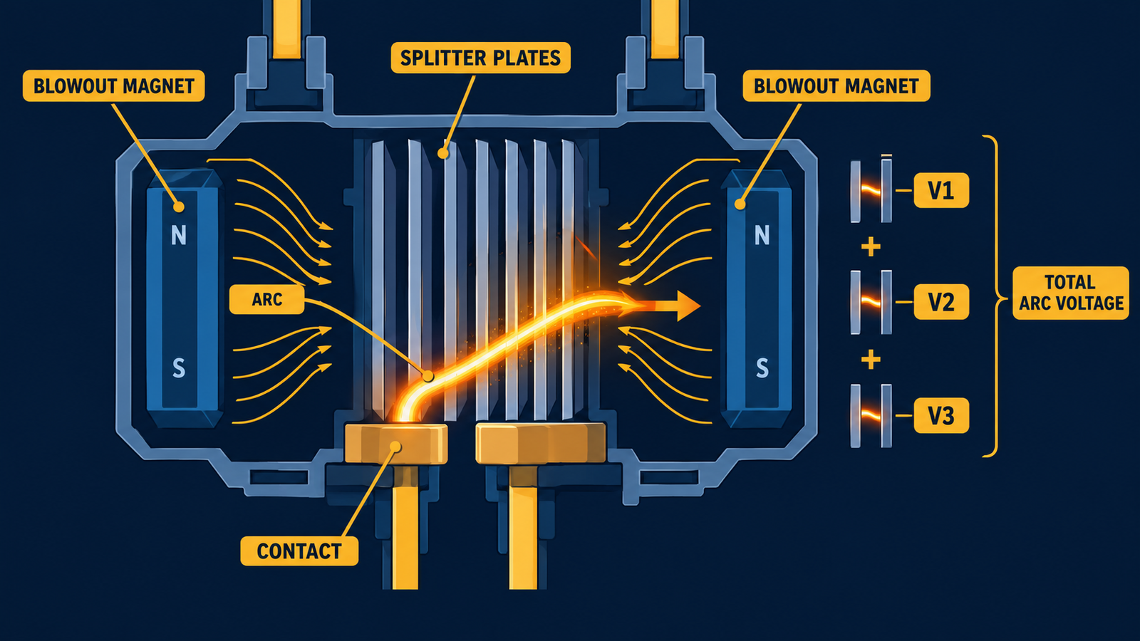
This is also why the same chassis can carry very different ratings. A common pattern in manufacturer DC tables: a frame rated several hundred amps in AC-3 duty at 690 V AC may be limited to tens of amps at 220 V DC, because the chute that coasts on zero crossings cannot sustain the same energy without them. For the anatomy of the chute and contact system in an AC frame, see this breakdown of contactor components, materials, and design logic.
Higher-voltage DC contactors — EV battery packs, DC fast chargers, energy-storage racks — often seal the contacts inside a hermetic chamber filled with hydrogen-rich gas. Hydrogen conducts heat well and has high dielectric strength, so it cools the arc quickly and helps the gap recover, which shrinks the chamber dramatically compared with an air-break design at the same rating. Sealing also keeps out the oxygen, moisture, dust, and salt that progressively oxidize open contacts and drive contact resistance upward over tens of thousands of operations.
The trade-off is serviceability: a sealed chamber cannot be opened, so the contacts cannot be inspected or replaced. When the electrical life is spent, the whole contactor is replaced. Open-air blowout designs are larger but allow contact inspection and replacement — a genuine maintenance advantage in panels that are serviced in place.
Every extra break in the current path adds another arc, another chute, and another set of arc voltages — all in series. This is the standard way to reach higher DC voltages with conventional hardware, and manufacturers publish DC ratings specifically for poles connected in series: ABB’s catalogue, for example, extends its motor-contactor range to 1,000 V DC-1 duty by connecting three main poles in series. The wiring detail matters as much as the count: all poles that participate in breaking must be connected in series between the load and the unearthed source terminal. If the poles straddle an earthed section, a single earth fault can leave one contact breaking the full load current on its own — a condition the contactor is not rated for.
The mirror mistake is wiring poles in parallel to gain current capacity. It does not work: the poles never share current equally, and the weakest path takes the arc. Series increases voltage; nothing simple increases DC current beyond the frame’s rating. For how DC and AC choices diverge at the control-circuit level, see this comparison of AC vs DC control circuits.
| Mechanism | How it extinguishes the arc | Typical use | Trade-off |
|---|---|---|---|
| Permanent-magnet blowout | Fixed field drags arc sideways off the contacts into the chute | Industrial DC contactors, traction | Polarized — reverse connection defeats the blowout |
| Series blowout coil | Field scales with load current, strong at high current | High-current breakers, large DC contactors | Weak field at low currents; adds resistance and heat |
| Splitter-plate chute | Splits arc into series short arcs; total arc voltage exceeds supply; cools plasma | Nearly all air-break DC contactors | Chute erosion over loaded-break life |
| Sealed gas / vacuum chamber | Hydrogen mix or vacuum cools arc and speeds dielectric recovery | EV, DC fast charge, energy storage, high voltage | Non-serviceable; whole unit replaced at end of life |
| Poles in series | Each break adds arc voltage; multiplies withstand voltage | 220–1,000 V DC systems on standard frames | Uses up poles; correct series/earth wiring is mandatory |
The failure mode is distinctive and usually expensive. An AC contactor opening a DC load builds an arc that never finds a zero crossing; the chute, sized for brief arcs, overheats and erodes; the arc can hold for hundreds of milliseconds or simply never extinguish, welding the contacts together or flashing over to the enclosure. The weld typically forms at the moment of disconnection under load — not during normal conduction — which is why operators report contactors that “weld shut when the machine is switched off.”
| Field symptom | Root cause in DC switching | Correct response |
|---|---|---|
| Contacts welded after switching off under load | No zero crossing; arc burned until contacts fused | Use a DC-rated contactor sized by category and time constant |
| Pip-and-crater contact pair after short life | Unidirectional DC metal transfer from anode to cathode | DC-rated contact materials and geometry; correct rating for duty |
| Chute plates blackened, arc marks outside the chamber | Arc energy exceeded chute design; blowout defeated | Check time constant and voltage against published DC tables |
| Arc flash at enclosure on opening | Arc blew out of the chamber or flashed over to frame | Verify polarity, series-break wiring, and enclosure clearances |
| Breaker or fuse never tripped, contactor destroyed | Contactor was expected to interrupt a short circuit | Coordinate with an upstream SCPD — a contactor is not a protective device |
If a panel is already showing these symptoms, the contactor troubleshooting guide covers the diagnosis and repair sequence.
DC selection runs on more variables than AC selection. Work through them in order — the first three decide everything downstream:
The last point applies on AC too — contactors handle switching duty, circuit breakers handle protection, and confusing the two roles is one of the most common panel-design errors.
| Mistake | Why it fails | What to do instead |
|---|---|---|
| Using an AC contactor on DC because “600 V AC covers 220 V DC” | AC and peak DC voltages are different quantities, and the arc physics do not transfer at all | Use only the manufacturer’s published DC rating table for the actual category and time constant |
| Choosing by thermal (continuous) current alone | Make/break duty at category current is the binding constraint | Size for the utilization category, including 2.5× make and break at supply voltage |
| Ignoring the L/R time constant | A 100 A DC-1 break and a 100 A DC-5 break stress the chamber by roughly 8× different energy | Determine τ before choosing; add a parallel resistor across large inductances if needed |
| Reversing polarity on a polarized DC contactor | Blowout magnets push the arc back onto the contacts instead of into the chute | Respect terminal polarity markings on every installation |
| Connecting poles in parallel for more current | Current never shares equally; one pole takes the arc | Series poles for voltage; select a bigger frame for current |
| Trusting the mechanical-life cycle count | Loaded DC breaks wear the contacts orders of magnitude faster | Request electrical life at rated DC voltage, current, and time constant |
AC switching is easy because the waveform cooperates: the current crosses zero and the arc dies on schedule. DC switching is hard because it never does — every DC break is a fight the contactor hardware has to win on its own, against both the supply and the energy stored in the circuit inductance. Magnetic blowout, splitter-plate chutes, sealed chambers, and series breaks are not extra features; they are the minimum machinery for raising arc voltage above the source and cooling the plasma faster than it can re-strike. Specify by voltage, current, utilization category, time constant, and polarity, and never substitute an AC frame into a DC load circuit.
Many real projects mix both worlds — a DC battery or control system feeding AC motor loads. For the AC side of the panel, the 3TF series AC contactor covers frequent motor starting and AC motor control to IEC/EN 60947-4-1, with OEM/ODM support for panel builders. For DC load circuits, always select a contactor from a published DC rating table.
Not above roughly 110 V DC. Current derating does not fix the physics — without a zero crossing, the arc voltage never rises enough to extinguish unless the hardware is built for it. Some manufacturers do publish limited DC-1 ratings for standard frames with poles connected in series; use only those published values, at the exact category and time constant stated, and nothing beyond them.
Three reasons stack up: longer contact gaps and deeper arc chutes are needed to stretch and cool an arc that never dies naturally; blowout magnets or coils take up space around the gap; and the sealed chambers used at higher voltages add housing volume. The bulk is not overengineering — it is the physical workspace the arc needs to be extinguished in.
Divide the circuit inductance in millihenrys by the resistance in ohms; the result in milliseconds is the time constant. If the datasheet does not list inductance, measure the current rise to 63.2% of steady state after applying voltage, or bound it by load class: resistive heaters around 1 ms, shunt motors around 2 ms, series motors up to 7.5 ms.
The blowout magnets (or the field from a series coil) push the arc in one fixed direction. With correct polarity, that direction is into the arc chute; with reversed polarity, the arc is blown back onto the contacts and the surrounding structure. Polarized designs carry terminal markings, and reversing them voids the breaking ratings.
No. Poles in parallel never share current equally because of contact-resistance differences, and the arc concentrates in the path that opens last. Only series connection helps in DC switching, and it helps voltage — not current. For more current, select a larger frame.
Far fewer than the mechanical-life figure suggests. Electrical life at rated DC voltage and current depends on the utilization category and time constant, and it is often hundreds of times lower than the mechanical cycle count. Ask the manufacturer for the loaded-break life curve at your exact duty — for many DC disconnect applications the relevant number is simply: will it break rated current once, under fault, after years in service?