Motor Thermal Damage Curve vs Relay Trip Curve
Six points, two lines, three conditions. Plot the thermal damage curve against the relay trip curve and know exactly what the overlaps mean.
Read More
Every terminal on a contactor carries a number or letter, and those markings are not decorative. They are a compressed wiring instruction: A1 and A2 are the coil, 13/14 is a normally-open auxiliary contact, 21/22 is normally-closed, 95/96 is the overload relay’s trip contact. Read them correctly and a panel can be traced, tested and modified without a drawing. Misread them and a stop circuit gets wired through a normally-open contact, or a PLC input ends up on the wrong side of a trip contact.
This guide covers the whole terminal language of a contactor — power poles, coil, auxiliary contacts and overload relay — across IEC 60947, NEMA and UL conventions, including where the three systems genuinely differ and where they only look different. It deliberately goes beyond the power-circuit markings alone: if you only need L1, L2, T1, T2 on the main poles, that is covered in what L1, L2, T1 and T2 mean. What follows is the rest of the device.
| Layer | Marking | Rule | Where it comes from |
|---|---|---|---|
| Power poles | L1/L2/L3 → T1/T2/T3, or 1/3/5 → 2/4/6 | Odd numbers on the line side, even on the load side | IEC 60947-4-1 practice; NEMA uses L/T letters |
| Coil | A1 and A2 (sometimes a second A2) | A1 is the control input; on DC coils A1 is normally positive | IEC 60947 convention; identical under NEMA/UL |
| Auxiliary contacts | 13/14, 21/22, 31/32, 33/34 … | First digit = contact number; last digit 1–2 = NC, 3–4 = NO | IEC 60947-5-1 / EN 50005 numbering |
| Overload relay | 95/96 (NC trip), 97/98 (NO alarm) | Fixed pair, outside the auxiliary numbering scheme | Long-standing European practice, now near-universal |
The important structural fact: contactors use two different numbering philosophies at once. Auxiliary contacts follow a rule you can decode and extrapolate. Overload relay trip contacts use a fixed historical pair that you simply have to know. Mixing the two up is the origin of most terminal-related wiring errors.
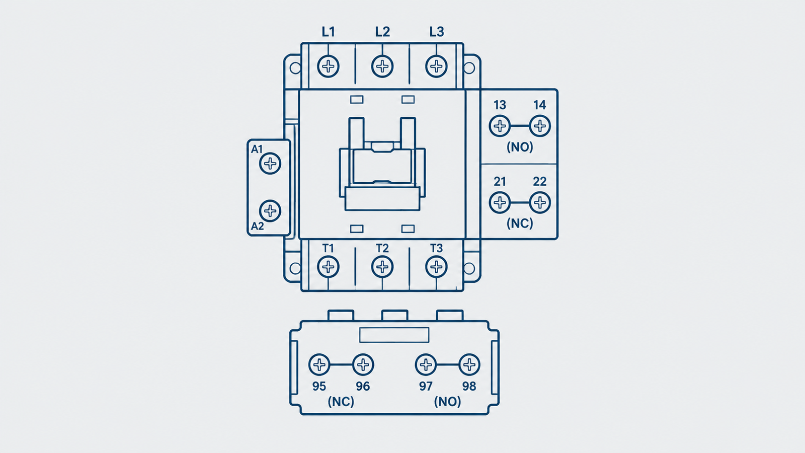
IEC auxiliary contact numbering is systematic. The tens digit identifies which auxiliary contact it is (1, 2, 3, 4 …). The units digit identifies the function and which side of that contact you are on:
So contact number 1 has an NC pair at 11/12 and an NO pair at 13/14. Contact number 2 has 21/22 (NC) and 23/24 (NO). Contact number 3 has 31/32 (NC) and 33/34 (NO). This is why 21/22 is universally NC on IEC-pattern contactors while 13/14 is universally NO — and why an auxiliary block labelled 43/44 is an NO contact belonging to contact number 4, not “the 43rd terminal”.
| Contact no. | NC pair | NO pair | Typical use |
|---|---|---|---|
| 1 | 11/12 | 13/14 | Seal-in (13/14), interlock drop-out (11/12) |
| 2 | 21/22 | 23/24 | Electrical interlock, PLC feedback |
| 3 | 31/32 | 33/34 | Indicator lamps, run signal |
| 4 | 41/42 | 43/44 | Second interlock, sequence logic |
| 5 | 51/52 | 53/54 | Star-delta changeover, two-speed logic |
| 6 | 61/62 | 63/64 | Extra feedback, safety monitoring |
| 7/8 | 71/72, 81/82 | 73/74, 83/84 | Special / mirror contacts on safety versions |
The contact number does not tell you whether the contact is physical (a real block clipped onto the front or side) or integrated into the contactor body. Both are numbered the same way, which is convenient: a 21/22 on a side-mounted block behaves exactly like a 21/22 moulded into the frame, and both are normally closed at rest.
The main poles carry the load, and two marking systems coexist. The letter system is what most buyers see on contactors sold internationally:
| Pole | Letter system | Numeric system | Note |
|---|---|---|---|
| 1st pole | L1 → T1 | 1 → 2 | Line side odd, load side even |
| 2nd pole | L2 → T2 | 3 → 4 | Same rule |
| 3rd pole | L3 → T3 | 5 → 6 | Same rule |
| 4th pole (where fitted) | L4 → T4 | 7 → 8 | Neutral or fourth phase pole |
The numeric system is older European practice and is still printed on many DIN-rail and modular devices. Its logic is the same one that governs auxiliary contacts: odd on the line side, even on the load side. That consistency is worth remembering, because it is the only part of the power-pole marking that carries a rule rather than a label.
What the markings deliberately do not tell you is polarity or phase sequence. A three-phase contactor will close happily with L1/L2/L3 swapped; the motor simply runs backwards. On a reversing assembly that is the whole point of the second contactor, which is why the reverse unit’s load terminals are wired in swapped order — as shown in reversing contactor arrangements.
Every IEC contactor coil has A1 and A2. The markings are the same under NEMA and UL practice, which makes the coil the one part of the device that is genuinely international.
Three details cause most of the confusion:
A thermal overload relay does not follow the 1–2 / 3–4 auxiliary rule. It uses a fixed historical pair:
| Terminal pair | Function | State at rest | Typical connection |
|---|---|---|---|
| 95 / 96 | Trip contact | Closed (NC) | In series with the contactor coil, or to a PLC trip input |
| 97 / 98 | Alarm / signalling contact | Open (NO) | Alarm lamp, PLC alarm input, remote indication |
95/96 opens when the relay trips, which is why it is wired in series with the coil in a conventional starter: the trip removes coil voltage directly, without relying on any control logic. If the same contact is instead wired to a PLC digital input, the trip no longer stops the contactor by itself — the PLC has to act on it. That is a design decision, not a wiring accident, and it belongs in the drawing.
The 97/98 alarm contact is a frequent omission. It exists so a trip can be reported without breaking the control circuit, which is what you want on a plant where an unannounced trip is the expensive part. The internal contact arrangement is described in how a thermal overload relay works.
For most of the device, the three systems agree. The differences are concentrated in four places:
Practical consequence: on an IEC device you can decode an unlabelled terminal from the number. On a NEMA-style definite-purpose contactor you cannot, and you should trace continuity rather than trust the print. The construction differences behind that are covered in definite purpose versus general purpose contactors.
| Trap | What happens | Check |
|---|---|---|
| Assuming 21/22 is NO because it is a higher number | Interlock logic inverted; machine can start in the wrong state | Units digit 1–2 is always NC; verify with a meter at rest |
| Wiring the seal-in contact to 21/22 | Contactor drops out as soon as the start button is released | Seal-in must be an NO contact — 13/14 |
| Landing the overload trip on 97/98 | Protection never operates; motor runs to failure | 95/96 is the NC trip pair |
| Swapping A1 and A2 on a DC coil with a diode suppressor | Suppressor conducts on power-up; control fuse blows | A1 positive on DC coils |
| Using the numeric 1/3/5 scheme as phase sequence | Motor runs backwards on a “correct” wiring job | Numbers define poles, not phase order |
| Assuming an integral auxiliary is field-configurable | Ordered a block that cannot be fitted, or removed one that is moulded in | Check the frame’s accessory list, not the terminal print |
If a device is already wired and behaving incorrectly, the fastest diagnostic is continuity at rest: every NC pair should read closed, every NO pair open, with the coil de-energised. That single test catches most of the traps above before any control logic is suspected. For the wider wiring sequence, see how to wire a contactor.
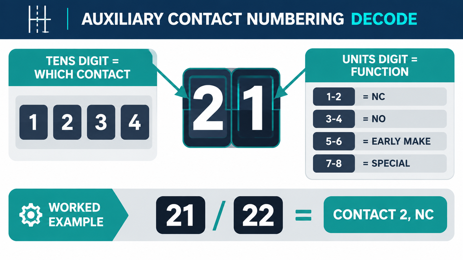
Take a four-pole frame with one integral NO auxiliary and a clip-on NC block, carrying these markings: 1/2, 3/4, 5/6, 7/8 on the power side, A1/A2 at the bottom, 13/14 on the integral auxiliary and 21/22 on the clipped block.
13/14 is NO, contact number 1 — the natural seal-in or feedback contact.21/22 is NC, contact number 2 — the natural interlock or “stopped” feedback contact.That reading is the whole value of the numbering system: from the print alone, the available functions and their rest states are known before a meter is connected. The contactor’s role relative to relays and breakers — and why it carries auxiliary contacts at all — is set out in auxiliary versus main contacts.
It is a normally-open (NO) auxiliary contact. The “1” is the contact number and the “3/4” indicates an NO function, so 13 and 14 are the two terminals of the same NO contact. It closes when the coil is energised.
Normally closed (NC). Units digit 1 or 2 indicates an NC contact, so 21/22 is closed at rest and opens when the contactor picks up. It is the standard choice for an electrical interlock or a “contactor is off” feedback signal.
Overload relays predate the harmonised auxiliary numbering and kept their own fixed pair: 95/96 for the NC trip contact and 97/98 for the NO alarm contact. The convention is now used worldwide, including on UL-listed devices.
A1/A2 is the coil — the control circuit that operates the contactor. L1/T1 (or 1/2) is a main power pole that carries the load current. They are electrically isolated from each other and must never be interconnected.
You need an NO contact, because the seal-in path must be open when the contactor is at rest and closed when it picks up. 13/14 or 23/24 are the usual choices; an NC pair such as 21/22 will make the contactor drop out as soon as the start button is released.
Partly. The coil (A1/A2) and the overload relay (95/96, 97/98) are the same. Auxiliary contacts on NEMA-style definite-purpose frames are often marked only NO and NC without numbers, and the power poles carry L1/L2/L3 → T1/T2/T3 rather than 1/3/5 → 2/4/6.
Learn one rule and one exception. The rule: on IEC auxiliary contacts, the first digit identifies the contact and the last digit identifies the function — 1/2 NC, 3/4 NO — which makes every number on the device decodable. The exception: overload relay terminals 95/96 and 97/98 carry fixed historical functions that the rule does not predict, and confusing them disables motor protection. Everything else — A1/A2 for the coil, odd-line/even-load on the power poles — is consistent enough to trust. For frames where this numbering applies across the range, the LC1-D series contactors page lists the pole and auxiliary configurations available, and the AC contactor category covers the full range.