1-Pole vs 2-Pole AC Contactors (HVAC): How to Choose
Pole count is decided by the wiring system, not the frame size. Compare 1-pole and 2-pole HVAC contactors, the bypass-bar construction and the safe replacement rules.
Read More
A contactor coil is a few henries of inductance carrying a standing current. When the control contact opens, that current has to stop immediately — and the coil responds with a voltage spike that reaches hundreds of volts on a small relay and several kilovolts on a large contactor. The spike pits the switching contact, corrupts nearby electronics, resets PLC inputs and eventually welds the control contact shut. A coil surge suppressor is a two-dollar component that prevents all of it, but choosing the wrong type creates a second problem: it can slow the contactor’s drop-out so much that a stop function no longer stops.
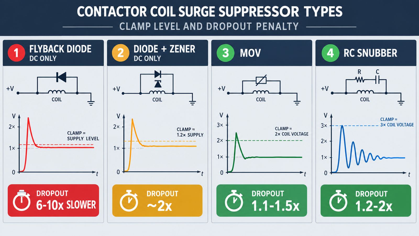
This guide covers the four suppression devices used on contactor coils — flyback diode, diode-plus-Zener, metal-oxide varistor (MOV) and RC snubber, plus the bidirectional TVS variant — with the clamp voltage and drop-out penalty of each, the selection rules for AC versus DC coils, and the leakage-current traps that show up in PLC panels. The devices discussed here protect the coil circuit; they have nothing to do with the load-side suppression that vacuum contactors need for motor insulation.
| Suppressor | Coil type | Clamps spike to | Drop-out time impact | Relative cost |
|---|---|---|---|---|
| Flyback diode | DC only | ≈ supply + 0.7 V | 6–10× slower — severe | Lowest |
| Diode + Zener (or TVS in series) | DC only | ≈ supply + VZ | ~1.5–2× — moderate | Low |
| MOV varistor | AC and DC | ≈ 2× Uc | 1.1–1.5× — small | Low–moderate |
| RC snubber | AC and DC | ≈ 3× Uc | 1.2–2× — small | Moderate |
| Bidirectional TVS | AC and DC | ≈ 2× Uc | Nearly none | Moderate |
The one-line rules: never put a plain diode across an AC coil — it conducts on every half-cycle and destroys itself. Never put a plain diode on any coil whose drop-out time matters. For AC coils, choose an MOV for clamp tightness or an RC snubber for dv/dt control. For DC coils where speed matters, use diode-plus-Zener rather than a plain diode.
The energy stored in the coil at the moment of break is E = ½·L·I². A 24 V DC contactor coil drawing 0.15 A with 0.5 H of inductance stores about 5.6 mJ — small, but delivered into an open circuit, the voltage rises until something breaks down. Without suppression, the same coil can spike to 300–500 V. A large AC contactor coil with more inductance and more current produces spikes well above 2 kV, fast enough (nanoseconds to microseconds of rise) to couple capacitively into adjacent wiring and appear as “random” resets in nearby electronics.
The suppressor’s job is to give that energy a controlled path: a clamped voltage the insulation can tolerate and a decay current that flows for a defined time. Every device in the table above is simply a different trade-off between how tightly it clamps and how long it lets the coil current keep flowing — and the drop-out time column is the price of the trade.
A diode wired reverse-parallel across a DC coil gives the decay current a one-diode-drop loop, so the spike is clamped to roughly the supply voltage plus 0.7 V. It is the cheapest suppression available and completely effective at protecting the contact. The cost is drop-out time: with nothing to dissipate the energy quickly, the coil flux decays through the diode loop and the armature hangs on until the holding force collapses naturally.
Measured examples in engineering literature put the penalty at 6 to 10 times the unsuppressed drop-out time — a 13.5 ms release becoming 97 ms with a plain diode. On a process valve or a lighting contactor nobody notices. On an emergency stop, an anti-plugging interlock, or a contactor that must open before a second one closes, that delay is a functional failure, not a nuance.
Adding a Zener diode (or a unidirectional TVS) in series with the flyback diode, oriented to oppose the decay current, forces the circulating current to build up a voltage equal to the Zener breakdown before it can flow. More voltage across the coil means faster current decay and faster mechanical release, while the total spike stays clamped to supply + VZ + diode drop. A Zener of roughly twice the supply voltage is the usual starting point: tight enough to protect the contact, steep enough to keep the release inside about twice the unsuppressed time. This is the standard fix for DC coils on safety-related switching.
A metal-oxide varistor is bidirectional and voltage-dependent: high resistance at normal coil voltage, low resistance above its varistor voltage. It clamps the break spike to roughly twice the coil’s rated voltage and adds little release delay (about 1.1–1.5× nominal). Because it is bidirectional, it works directly on AC coils — where a plain diode is impossible — and on DC coils alike.
Selection follows the coil voltage, not the bus voltage. The varistor voltage must sit above the AC peak (Vrms × √2) with margin, and below the coil insulation’s withstand. Common catalogue pairings: a 275 VAC MOV (for example the S14K275 class) for a 230 V AC coil, a 150 V class device for a 120 V AC coil, and a 30–33 V device for a 24 V DC coil. For repetitive switching, size the MOV’s joule rating at roughly ten times the coil’s per-break energy — the device also absorbs upstream switching transients, and an undersized MOV degrades to open circuit over months of duty.
An RC snubber is a series resistor and capacitor wired across the coil. At break, the coil current charges the capacitor, and the resistor both limits the inrush into it and damps the LC ringing. It clamps less tightly than an MOV (about 3× Uc) and adds a comparable small release delay (1.2–2×). Its distinctive strength is controlling the rate of voltage rise, which is exactly what confuses electronics and causes false triggering across cables — and its distinctive weakness is leakage: the capacitor passes current at mains frequency continuously while the coil is off. That leakage is usually a few milliamps, small against a contactor’s holding current but large against a PLC input’s threshold or a neon indicator’s. See the leakage section below.
For the coil-voltage context behind these ratings — 24 V control versus 230/400 V coils, and how the coil is specified — see contactor coil voltage explained.
Wiring the suppressor across the coil terminals (A1–A2) protects the switching contact and everything else in the loop, keeps the protection with the device when the contactor is reused in another panel, and for clip-on accessories requires no extra wiring at all. Wiring it across the switch instead protects only that one contact, leaves the coil wiring radiating the spike, and is the reason a panel can contain one quiet contactor and one that resets the HMI every time it drops out.
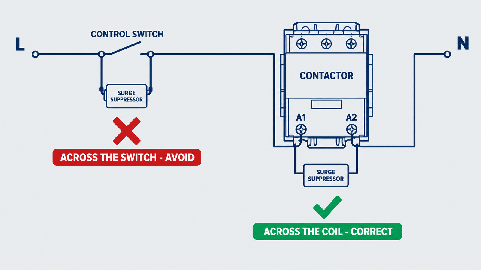
Two placement rules complete the picture. First, mount the suppressor as close to the coil terminals as the accessory allows — lead length adds inductance and degrades the clamp. Second, check whether the coil already has factory-fitted suppression before adding an external device: stacking an external MOV across a factory-fitted one makes the two share current unevenly, and an external RC across a factory RC changes the effective time constant. Verify in the contactor’s accessory documentation, not by looking at the housing.
Three real failure patterns come not from the spike but from the suppressor’s off-state behaviour:
Symptoms like these sit alongside other coil-side faults; the diagnostic sequence in contactor troubleshooting covers the buzzing and chattering cases that leaky suppression mimics.
| Mistake | What happens | Correction |
|---|---|---|
| Plain flyback diode on an AC coil | Conducts every half-cycle, diode fails short | AC coils need bidirectional devices: MOV, RC or bidirectional TVS |
| Plain diode on an e-stop contactor’s DC coil | Drop-out 6–10× slower; stop function timing fails | Diode plus Zener, or MOV sized for the coil |
| Suppressor wired across the switch instead of the coil | Coil wiring still radiates; other contacts unprotected | Mount across A1–A2 at the coil |
| MOV sized by bus voltage instead of coil voltage | Clamp too high (no protection) or too low (MOV cooks) | Select on the coil’s rated control voltage |
| Ignoring RC leakage in a PLC output loop | Relay never drops out; phantom inputs; glowing LEDs | Check leakage vs drop-out current; use bleed resistor or MOV |
Not strictly — a coil switched by a robust contact with nothing sensitive nearby can run unsuppressed for years. But every break event erodes the switching contact and radiates a spike, so suppression is cheap insurance wherever a contactor is switched by electronics, sits near PLC or instrumentation wiring, or switches frequently. Treat it as default-on and justify leaving it out, not the reverse.
No. A plain diode conducts on the negative half-cycle and destroys itself immediately, usually taking the control fuse with it. AC coils need a bidirectional device: MOV, RC snubber or bidirectional TVS.
Most likely a plain flyback diode on a DC coil — the 6–10× release penalty is inherent to that topology. Replace it with a diode-plus-Zener combination (Zener roughly twice the supply voltage) or an MOV to keep protection while restoring release speed.
Directly across the coil terminals A1 and A2, with the shortest leads the accessory allows. Clip-on modules that mount on the contactor body are preferred because they keep the loop short and stay with the device.
Yes, gradually. Each surge degrades the zinc-oxide structure slightly; the device eventually fails high-resistance (open), which silently removes the protection. For high-cycle duty, size the joule rating with margin — about ten times the coil’s per-break energy — and include the suppressor in periodic checks on critical panels.
No. Suppression must sit at each coil, because the spike is generated at each coil at the moment of its own break. A shared device across a group of coils clamps only the loop voltage and protects none of them properly.
Coil suppression protects the control circuit from the coil’s own break spike. Load-side protection — RC networks or MOVs at the motor terminals — protects motor insulation from switching overvoltages, which matters mainly for vacuum contactors. The two are separate devices in separate circuits and one does not substitute for the other.
MOV if you want the tightest clamp and minimal release delay; RC if dv/dt control matters more — long control cables, sensitive electronics nearby. Both are acceptable; check the leakage constraint before choosing the RC.
Coil suppression is a two-variable decision: how tightly you need the spike clamped, and how fast the contactor must release. AC coils get MOV, RC or bidirectional TVS; DC coils with a speed requirement get diode-plus-Zener; DC coils without one can take the cheap plain diode. Size to the coil voltage, mount across A1–A2, and check the leakage arithmetic in PLC loops. Do those five things and the panel stops generating its own interference — permanently. For contactors with factory suppression options across the frame range, the 3TF series page lists the coil and accessory configurations available. For the AC-versus-DC coil design differences behind these choices, see AC versus DC contactors compared.