Types of Modular Contactors: A Practical Selection Guide
Types of modular contactors explained: poles, AC-7a vs AC-7b duty, NO vs NC contact forms, latching types and coil options, with an application-to-type selection matrix.
Read More
An AC contactor is a simple idea with surprisingly engineered internals: an electromagnetic coil pulls a moving core against a return spring, and that movement closes silver-alloy main contacts that carry the load current. What separates a contactor that lasts a million operations from one that welds shut after a few thousand is decided entirely inside the AC contactor — the choice of core material, the contact alloy, the arc chute geometry, and the springs that control every make-and-break. This article takes the cover off an AC contactor and explains each key component, the material it is made from, and the design logic behind it. If you are comparing contactors for motor or HVAC duty, this background makes the AC contactor datasheet figures — electrical life, utilization category, coil voltage — much easier to read.
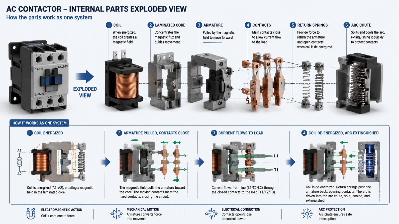
Every AC contactor, from a 9 A DIN-rail unit to a 630 A frame, runs the same operating sequence:
Each step depends on a different subsystem, and each subsystem is a materials-engineering decision. Walking through them in order is the clearest way to understand what is actually inside.
The electromagnetic system is the “motor” of the contactor. It converts electrical energy into the mechanical force that moves the contacts. It has three parts that must be designed together.
The coil is wound from insulated copper magnet wire — the standard is oxygen-free copper for its low resistivity and stable temperature behavior. The number of turns and the wire gauge set the coil’s rated voltage: 24 V AC, 110 V AC, 220 V AC and 380 V AC are the common control voltages on industrial panels. The wire enamel must survive continuous heat, so manufacturers use Class F (155 °C) or Class H (180 °C) insulation. The coil is the most common failure point on the whole device because it fails open if it overheats, and overheating usually traces back to a low or intermittent control voltage that stops the contactor from sealing properly — the topic covered in our guide on contactor coil failure and troubleshooting.
The magnetic core is not one solid block of iron. It is a stack of thin silicon-steel laminations, typically 0.35–0.5 mm thick, insulated from one another. AC flux changes direction 100 or 120 times per second, and a changing flux induces circulating eddy currents in a solid core. Those eddy currents waste energy as heat — lamination breaks the current paths and cuts eddy-current losses by roughly 80–90%. The same logic explains why AC and DC contactors are built differently: a DC coil produces steady flux, so DC contactors can use a solid core, while AC contactors cannot.
One detail that surprises most people who open a contactor is a single-turn copper ring, called the shading ring or shading coil, embedded in the face of the fixed core. AC magnetic force passes through zero twice per cycle; without the shading ring, the armature would release and re-seal 100 times per second and the contactor would chatter loudly and wear out quickly. The ring carries an induced current that produces a phase-shifted flux, so the combined pull never drops to zero. When a contactor starts humming badly, a cracked or missing shading ring is one of the first suspects — a sign covered in detail in our article on signs of a failing AC contactor.
The contacts are the working surface of the contactor — the parts that actually make and break the load current. Their material determines electrical life more than any other single factor.
Main contacts are silver-based because silver offers the best balance of conductivity, thermal performance and resistance to arc erosion. Bare silver is too soft and welds too easily, so manufacturers add alloying or oxide particles. The three families you will meet on datasheets are:
This material choice is also why the utilization category on the nameplate matters. A contactor specified for AC-1 to AC-4 duty has been validated against the exact switching stresses — resistive, motor starting, plugging and jogging — that the contact alloy will see.
Auxiliary contacts are mechanically linked to the main contacts but switch only the low-current control circuit — typically 6–10 A. They provide the feedback that PLCs, indicator lamps and interlocking logic need: a normally open (NO) auxiliary closes when the contactor pulls in, a normally closed (NC) opens. Standard frames offer 1NO+1NC, 2NO+2NC or 4-pole arrangements. They are usually the same silver-alloy system but sized down, because control circuits still break inductive DC loads that erode contacts.
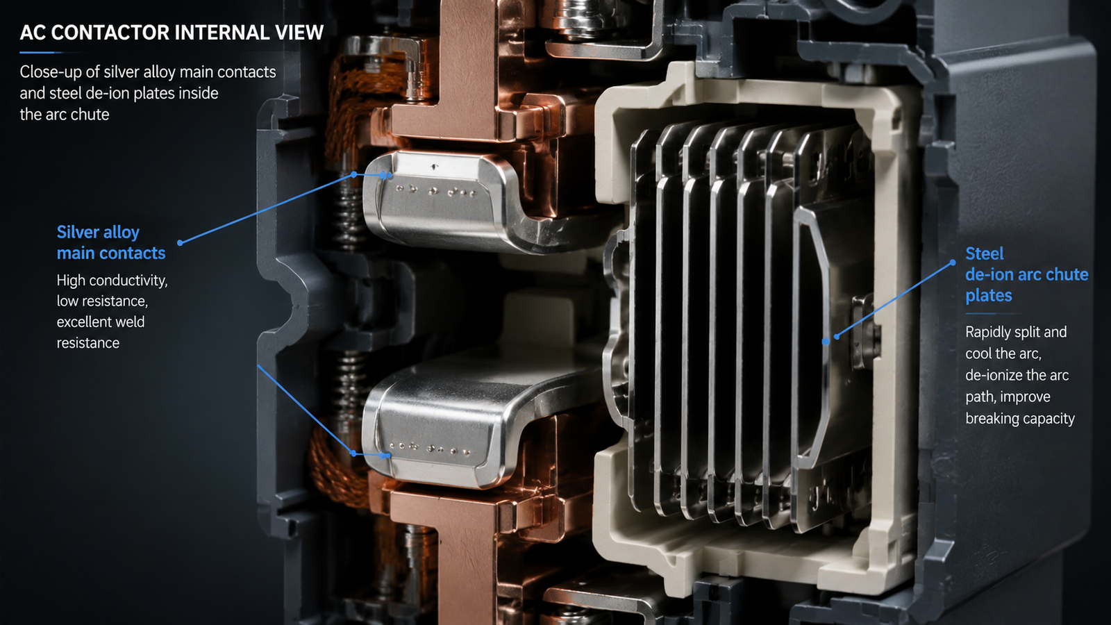
When contacts open under load, the current does not stop instantly. The collapsing magnetic field of the motor or transformer forces the current to keep flowing across the widening gap as an electric arc — a plasma that can exceed 5,000 °C at the contact surface. If nothing stopped it, the contacts would erode away in a few hundred operations.
AC has one huge advantage here: the current naturally crosses zero every half cycle. The arc chute — a stack of steel de-ion plates arranged like a ladder above the contacts — exploits this. Its magnetic field pulls the arc upward into the plates, which split one long arc into several short series arcs. Each short arc needs more voltage to sustain, so at the next zero crossing the arc cannot re-ignite and dies. That is why a contactor’s arc chute is directly above the contacts and why you should never mount a contactor with the chute blocked. DC systems get no zero crossing, which is exactly why DC contactors need magnetic blow-out coils and heavier arc hardware — another reason the AC versus DC distinction is a fundamental design fork.
Springs are the unsung parts of a contactor. The return spring stores the energy that opens the contacts the instant the coil releases, so its rate sets the release speed and the minimum dropout voltage. Separately, small contact springs press the moving contacts against the fixed contacts with a controlled force — typically a few newtons for small frames up to tens of newtons for large ones. That pressure is what keeps contact resistance low: too little pressure and the contacts run hot, too much and the armature cannot pull in at low coil voltage. Quality contactors tune this force-travel curve carefully, which is why a cheap contactor can feel “loose” and a premium one clicks shut with a crisp, consistent snap.
The housing does far more than look neat. It provides creepage and clearance insulation between live parts, mechanical support for the magnet system, and arc containment if an internal fault occurs. Housings are molded from flame-retardant engineering plastics — PA66 or nylon compounds rated UL 94 V-0 — that self-extinguish and hold their shape under heat. Terminal hardware is brass or plated copper sized to carry the rated current without excessive temperature rise, and the whole assembly is rated IP20 for finger-safe panel use, with higher IP ratings available for dustier environments. When you compare 3TF series magnetic AC contactors or similar frames side by side, differences in mold quality, terminal plating and ribbing density are usually visible even before you look at the electrical data.
| コンポーネント | Typical Material | Design Job |
|---|---|---|
| Coil winding | Oxygen-free copper, Class F/H enamel | Produce the magnetic pull; survive continuous heat |
| Core | Laminated silicon steel (0.35–0.5 mm) | Concentrate flux; cut eddy-current losses in AC |
| Shading ring | Copper single-turn loop | Hold armature sealed through AC zero crossings |
| Main contacts | AgSnO₂ / AgNi / AgCdO on copper | Make and break load current with low erosion |
| Auxiliary contacts | Silver alloy, reduced size | Switch control and feedback circuits |
| Arc chute | Steel de-ion plates | Split and cool the arc to extinction at zero crossing |
| Springs | Spring steel / stainless steel | Return the armature and set contact pressure |
| Housing | Flame-retardant PA66 / nylon (UL 94 V-0) | Insulate, support and contain arcs |
If you are evaluating a contactor — either on the bench or during a teardown — check the parts above in this order: look at the contact faces for pitting or silver loss, inspect the arc chute for blackened or fused plates, listen for a clean pull-in without buzz, and measure the coil. A practical walkthrough of coil resistance and contact continuity checks is in our guide on how to test an AC contactor with a multimeter, and the contactor wiring guide shows how the coil and auxiliary contacts connect into a real control circuit.
An AC contactor is engineered around a few decisive materials choices. The laminated core and shading ring tame AC’s pulsating magnetic field, the silver-alloy contact system determines electrical life under a given utilization category, the arc chute exploits the AC zero crossing to kill the arc, and the spring system controls contact pressure and release speed. Once you can look inside an AC contactor and read these choices, datasheet terms such as AC-3 electrical life, contact alloy and coil voltage stop being abstract — they tell you exactly how the device was designed to be used.
The main parts are the electromagnetic system (coil, laminated core and shading ring), the contact system (main and auxiliary contacts), the arc chute with de-ion plates, the return and contact springs, and the insulating housing with terminals.
Because AC flux changes direction 100 or 120 times per second, a solid core would waste energy on eddy currents. Thin insulated silicon-steel laminations break the current paths and cut eddy-current losses by roughly 80–90%, keeping the core cool.
Silver-based alloys. AgSnO₂ (silver tin oxide) is the modern standard for motor and HVAC duty, AgNi suits lighter resistive loads, and the older AgCdO is being phased out because cadmium is restricted under RoHS.
A steady low hum usually points to a damaged or missing shading ring, loose laminations, or low coil voltage that prevents the armature from sealing fully. All three cause the magnetic pull to fluctuate and the armature to vibrate.
The arc chute is a stack of steel de-ion plates above the contacts. It pulls the switching arc into the plates, splits it into short series arcs, and lets the AC current zero crossing extinguish it — protecting the contacts from erosion.