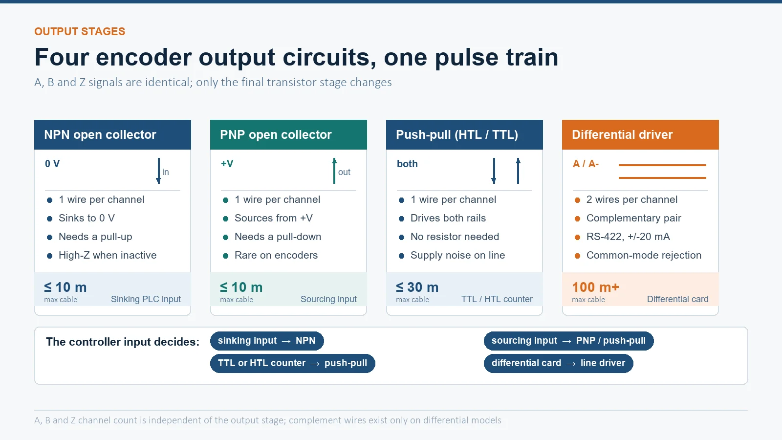
The encoder does not decide its output type – your controller does. An incremental encoder presents the same A, B and Z pulses through one of four output stages: NPN open collector (sinking, needs a pull-up, about 10 m of cable), PNP open collector (sourcing, needs a pull-down, rare on encoders), push-pull or totem-pole (active in both directions, HTL 10-30 V or TTL 5 V, about 30 m), and differential line driver (RS-422, A/A-, B/B-, Z/Z-, 100 m or more with common-mode rejection). Match the stage to the input circuit and the cable run, and the counter works first time.
Why the Output Stage Decides the Order
Two encoders with identical resolution, shaft and IP rating can be electrically incompatible with the same PLC. The mechanical drawing is the same, the pulse trains are the same, and only the last stage – the transistor circuit that drives the cable – differs. That stage sets three things that the rest of the system cares about: the logic level the controller must see, whether the encoder sinks or sources current, and how much electrical noise the signal will survive on the way down the machine.
The catalogue of a rotary encoder range normally lists the output form as a separate ordering position, exactly because it is a configuration choice and not a fixed feature of the model. Before ordering, find the input specification of the receiving device – not the encoder’s “recommended” output. This one step prevents most first-article failures.
The Four Output Types Compared
All four stages sit behind the same optical or magnetic sensing element. What changes is the last transistor pair and therefore the wiring, the supply range and the maximum cable length.
| パラメータ | NPN open collector | PNP open collector | Push-pull (totem pole) | Differential line driver |
|---|---|---|---|---|
| Output wires per channel | 1 (single ended) | 1 (single ended) | 1 (single ended) | 2 (true and complement) |
| Behaviour | Sinks to 0 V, high impedance when off | Sources from +V, needs pull-down when off | Actively drives both rails | Drives a balanced pair, one line inverted |
| Typical supply | 5, 12 or 24 V | 5, 12 or 24 V | TTL 5 V or HTL 10-30 V | 5 V to RS-422, or supply-matched HTL differential |
| Current per channel | 20-50 mA typical | 20-50 mA typical | +/- 20-50 mA | +/- 20 mA minimum, +/- 60 mA typical with an RS-422 driver |
| Logic levels | Set by the external pull-up | Set by the external pull-down | Low below 0.4 V, high above V+ minus 0.5 V (HTL: high above V+ minus 3.5 V) | Differential, about 2.5 V or more between pair |
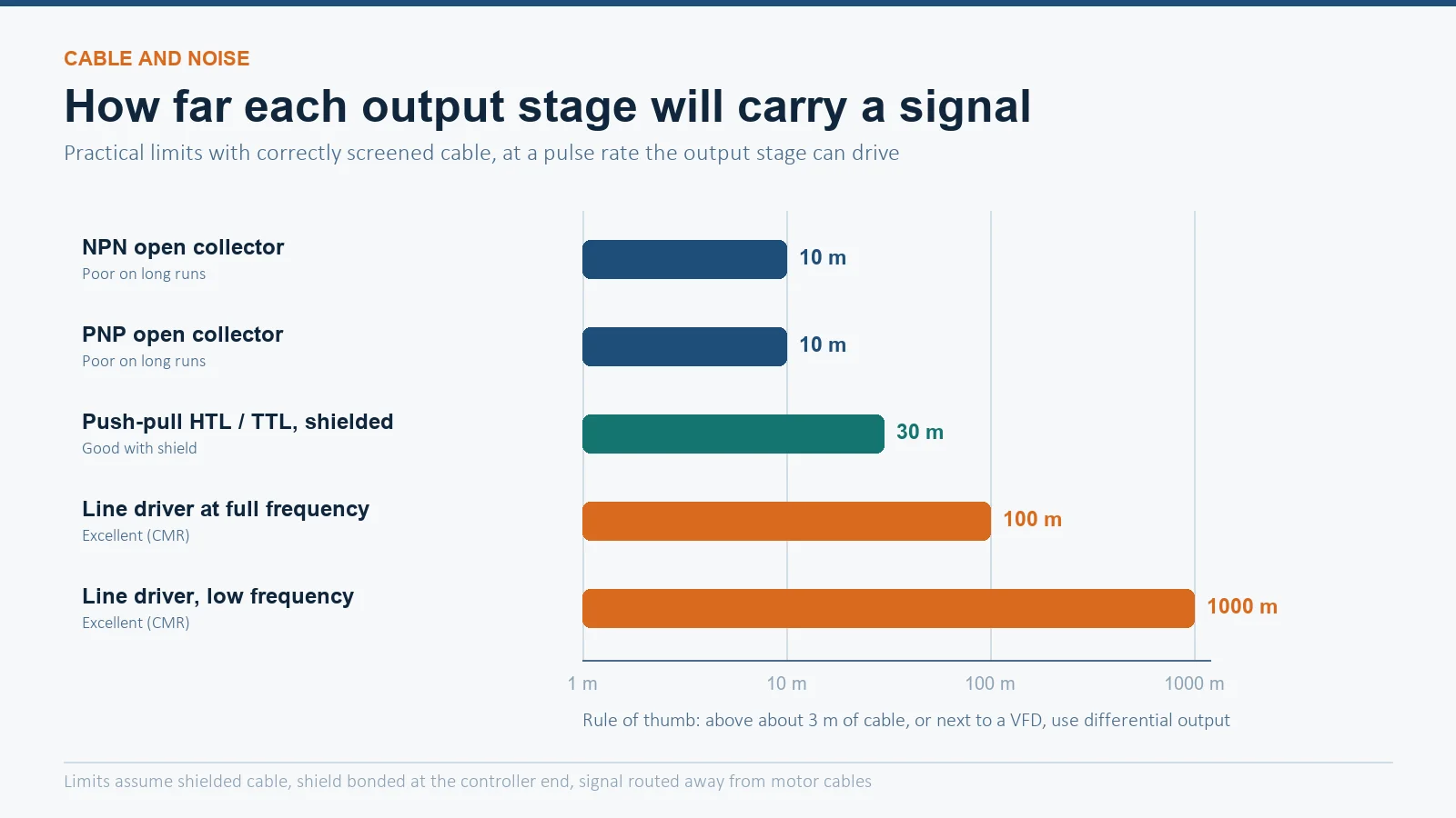
| Practical cable limit | About 10 m | About 10 m | About 30 m with shielded cable | 100 m or more at full frequency, up to about 1 km at low frequency |
| Noise immunity | Poor on long runs | Poor on long runs | Good with a shield, exposed to supply noise when high | Best – common-mode rejection |
| Typical controller input | Sinking (NPN) DC input | Sourcing (PNP) DC input | TTL or HTL DC input, fast counter | Differential counter card, VFD or servo PG input |
NPN Open Collector: The Sinking Default
An NPN open collector output is a single transistor with its emitter at 0 V and its collector brought out to the terminal. When the channel is active the transistor conducts and pulls the output down to 0 V; when it is inactive the output floats. The high level does not exist inside the encoder – it is created by a pull-up resistor at the receiving end, usually built into the PLC input card.
- Level shifting is the hidden benefit. Because the high level comes from the pull-up, the same encoder can run on a 5 V supply and still deliver a 24 V signal, as long as the pull-up goes to 24 V and the transistor can withstand it.
- The pull-up sets the rise time. A large external resistor with a long cable produces a slow rising edge and a soft pulse. This is the real reason open-collector encoders are quoted at about 10 m of cable, not a rule about voltage drop.
- The “pull-up” variant exists. Some models include the resistor internally, typically 1.5-2.2 kΩ, which removes the wiring but also removes the level-shifting option.
- NPN is not PNP. The two are opposite transistor polarities and cannot be substituted without changing the input circuit or adding an interface.
NPN remains common because a large share of low-cost PLC and counter inputs in Asia are sinking inputs designed for exactly this output. It is a good match for short cable runs inside a panel and a poor match for a 20 m run down a welding cell.
PNP Open Collector: Sourcing, and Rare on Encoders
A PNP output has its emitter at the positive supply and sources current into the load; the low level is created by a pull-down resistor at the receiving end. It matches sourcing (PNP) DC input modules, which are the default on much European machinery. On encoders it is far less common than NPN – many catalogue ranges simply do not offer it, and a push-pull unit is used instead when a sourcing behaviour is needed. If a drawing specifies PNP and the chosen model only offers push-pull, the push-pull version will drive a sourcing input correctly; the reverse is not true.
Push-Pull (Totem Pole): HTL and TTL
A push-pull stage uses two complementary transistors per channel, so the output is actively driven high and actively driven low. That gives clean edges, no external resistor, and the ability to drive a longer cable than an open collector – typically up to about 30 m with shielded cable. It comes in two voltage families that are not interchangeable:
| Family | Supply | Low level | High level | Typical controller |
|---|---|---|---|---|
| TTL push-pull | 5 V DC | Below 0.4 V | Above 2.5 V | 5 V counter input, microcontroller, motion card |
| HTL push-pull | 10-30 V DC, normally 24 V | Below 3 V | Above V+ minus 3.5 V | Siemens, Beckhoff and other 24 V DC input cards |
The weakness of push-pull is that when the output is high it connects the supply rail to the signal line. Any ripple, spike or switching noise on the encoder’s 24 V supply appears directly on the signal, which is fine in a clean panel and marginal next to a variable frequency drive. Use shielded cable, keep the encoder supply separate from contactor coils, and do not run the signal alongside motor cables. Where the run is long or the electrical environment is hostile, the differential stage is the correct answer.
Differential Line Driver: RS-422 and Long Cable
A line driver produces two complementary signals per channel – A and A-, B and B-, Z and Z- – on a twisted pair. The receiver looks only at the difference between the two wires, so noise coupled equally into both conductors cancels out. That common-mode rejection is why a line driver survives cable runs that destroy a single-ended signal: 100 m or more at full pulse frequency, and up to about 1 km when the frequency is low.
- RS-422 at 5 V is the usual implementation, with driver families such as 26LS31 or AM26C31 delivering about +/- 60 mA and a guaranteed +/- 20 mA minimum into the pair.
- HTL differential variants exist for 24 V systems and behave the same way electrically, with a larger voltage swing.
- Cable matters as much as the driver. Twisted pairs with an overall shield, shield bonded at one end to avoid a ground loop, and correct termination at the receiver.
- It cannot feed a single-ended input directly. A PLC sinking or sourcing DC input needs a receiver or interface module between the encoder and the card.
Any application with a VFD, servo drive, long cable tray runs or a cable longer than roughly 3 m benefits from differential output. Where an existing インクリメンタルエンコーダ is being replaced on a machine that already has twisted-pair wiring, the line-driver version is usually the drop-in choice, provided the receiving card has a differential input.
Matching the Output to Your PLC or Counter
Mismatches fail in a small number of predictable ways: no count at all, counting in one direction only, counts that appear at low speed and stop at high speed, or random counts when a nearby motor starts. The table below maps the common combinations.
| Controller input | Works directly | Does not work directly | Fix |
|---|---|---|---|
| Sinking (NPN) DC input module | NPN open collector, push-pull | PNP open collector | Use NPN or push-pull, or add an interface module |
| Sourcing (PNP) DC input module | PNP open collector, push-pull | NPN open collector | Use push-pull, or add a pull-up with inverted logic if the counter allows it |
| 24 V HTL fast counter input | HTL push-pull, HTL differential | 5 V TTL | Level converter, or order the HTL variant |
| 5 V TTL counter input | TTL push-pull, 5 V line driver | 24 V HTL | Level converter, or 5 V regulated output option |
| Differential counter card or VFD PG card | Line driver | Any single-ended output | Order the differential variant; a single-ended signal into a differential card usually reads as no signal |
Cable Length, Frequency and Noise
Output type sets the ceiling on cable length, but the pulse frequency sets the ceiling on the whole system. Convert before you specify: pulses per second equals PPR multiplied by RPM divided by 60. A 1024 PPR encoder at 1,500 rpm produces 25.6 kHz per channel, and a controller decoding A and B in quadrature sees 102,400 edges per second – which is where the input filter of a standard DC module stops keeping up and a high-speed counter input becomes mandatory.
Practical rules that prevent most noise faults:
- Screen the encoder cable and bond the shield at the controller end, not both ends.
- Keep the encoder cable at least 200 mm away from motor and VFD output cables where they run in parallel; cross at right angles where they must cross.
- Feed the encoder from a clean 24 V supply, not from the same rail as contactor coils or solenoid valves.
- Above roughly 3 m of cable, or anywhere a drive is present, prefer differential output over single ended.
- For long runs, use twisted pairs with the complement signal in the same pair – this is why a six-wire differential cable is not the same as a six-wire single-ended cable.
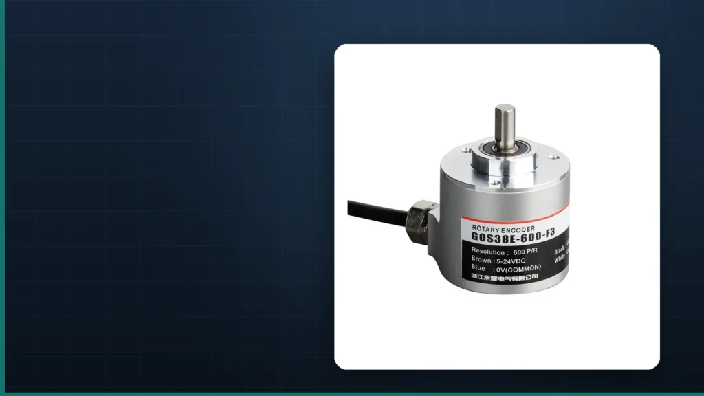
Where a wide supply range is useful – the same encoder running from 5 V on a bench and 24 V in the panel – check the model’s supply specification rather than assuming. A model such as the GOS38D incremental encoder is specified from 5 V to 26 V with A, B and Z square-wave outputs, while a sealed IP67 unit such as the GOS38E encoder is offered with push-pull output for washdown and outdoor machinery.
A, B and Z: What the Extra Channels Buy You
Output type decides how the pulse is transmitted; channel count decides what the pulse can tell the controller.
- A and B are two pulse trains offset by 90 electrical degrees. The offset gives direction: if A leads B the shaft turns one way, if B leads A it turns the other. Decoding both edges of both channels multiplies the resolution by four, so a 1000 PPR encoder yields 4,000 counts per revolution.
- Z, also called the index or zero pulse, occurs once per revolution and gives an absolute reference for homing. Without it, position is only relative to wherever the machine was when the counter was reset.
- Complementary outputs (A-, B-, Z-) exist only on differential models and are what makes the common-mode rejection possible; they carry no additional position information.
If the application needs absolute position after a power cycle, an incremental encoder is the wrong family regardless of output stage – the difference is covered in absolute versus incremental encoder. For wiring conventions on drawings, the terminal arrangement is summarised in the encoder symbol guide.
Selection Checklist by Application
| 申し込み | Recommended output | 理由 |
|---|---|---|
| Conveyor or packaging machine, PLC in the same panel, cable under 5 m | NPN open collector or push-pull | Short run, sinking input card, lowest cost |
| Machine with a VFD, cable run 5-30 m | Push-pull HTL, shielded | Clean edges into a 24 V counter, adequate for the distance |
| Long cable tray run, crane travel, 30 m or more | Differential line driver | Common-mode rejection is the only reliable option at that length |
| Servo or CNC feedback into a differential PG card | Differential line driver, 5 V | The card expects RS-422 levels and a complement signal |
| European PLC with sourcing inputs | Push-pull or PNP | Matches the sourcing input family |
| Washdown or outdoor machine | Push-pull, IP67 housing | Sealing and a driven output that tolerates a longer cable |
Once the output stage is fixed, the remaining choices are mechanical and optical: shaft or hollow bore, flange, PPR, and the load the shaft will see. Those are covered in the rotary encoder guide and in five practical tips for choosing an incremental encoder.
結論
Choose the output stage from the controller’s input circuit and the cable length, then choose the encoder. NPN open collector for a sinking input and a short run; push-pull HTL or TTL for a driven 24 V or 5 V signal up to about 30 m; differential line driver whenever the cable is long or a drive is nearby. Getting this one ordering position right removes the most common class of incremental encoder failure – a mechanically perfect encoder that the controller cannot read.
よくあるご質問
Can I use an NPN encoder with a PNP input?
Not directly. NPN sinks current to 0 V and PNP input expects current sourced into it, so the input sees no valid signal. Either order the push-pull or PNP version, or insert an interface module. A pull-up resistor with inverted logic can work on a counter that allows the inversion, but it is a workaround, not a specification.
Is push-pull better than open collector?
It is better for signal quality and cable length and it removes the external resistor, which is why it costs more. It is not automatically better for the application: if the PLC has a sinking input and the run is short, an NPN open collector works perfectly and costs less.
How long can an encoder cable be?
About 10 m for open collector, about 30 m for push-pull with shielded cable, and 100 m or more for a differential line driver at full frequency, extending to roughly 1 km when the pulse frequency is low. These are practical limits with correct screening, not guaranteed figures.
Why does my counter work at low speed and stop at high speed?
Usually the input filter or the output stage cannot follow the pulse rate. Check pulses per second – PPR times rpm divided by 60 – against the counter’s maximum input frequency, and check whether the pull-up resistor and cable capacitance are rounding off the edges. A high-speed counter input and a push-pull or line-driver encoder solve both causes.
Does a differential encoder give better resolution?
No. The complement signals carry the same information inverted, for noise rejection only. Resolution comes from PPR and from how many edges the controller decodes – one, two or four per cycle.
What is the difference between HTL and TTL output?
HTL is a push-pull output running from 10-30 V, normally 24 V, with logic levels near the supply rails; it suits 24 V industrial input cards. TTL is a 5 V push-pull output with a logic high above 2.5 V, used by 5 V counters and motion cards. They are not interchangeable without a level converter.