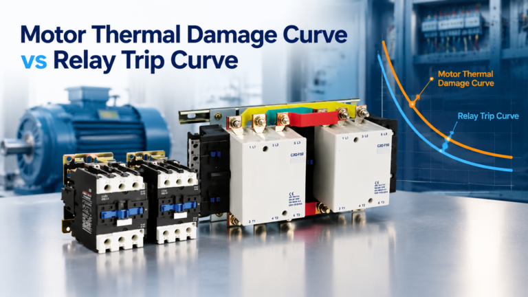
Motor Thermal Damage Curve vs Relay Trip Curve
Six points, two lines, three conditions. Plot the thermal damage curve against the relay trip curve and know exactly what the overlaps mean.
Read More
Most overload relay failures are not failures at all. They are setting errors, and they are made on the day the panel is commissioned, when the dial is turned to whatever stops the trip rather than to what the motor actually draws. This guide covers the overload relay setting decisions that are made in the field: where the dial belongs, what ambient compensation does and where it stops working, and how to tell a genuine nuisance trip from a motor that is telling you something.
If you are still choosing which relay to buy, start with the AC contactor and motor protection range for the device families, then come back here for the commissioning numbers. Setting assumes the hardware is already right; no dial position can compensate for a relay whose range does not cover the motor current.
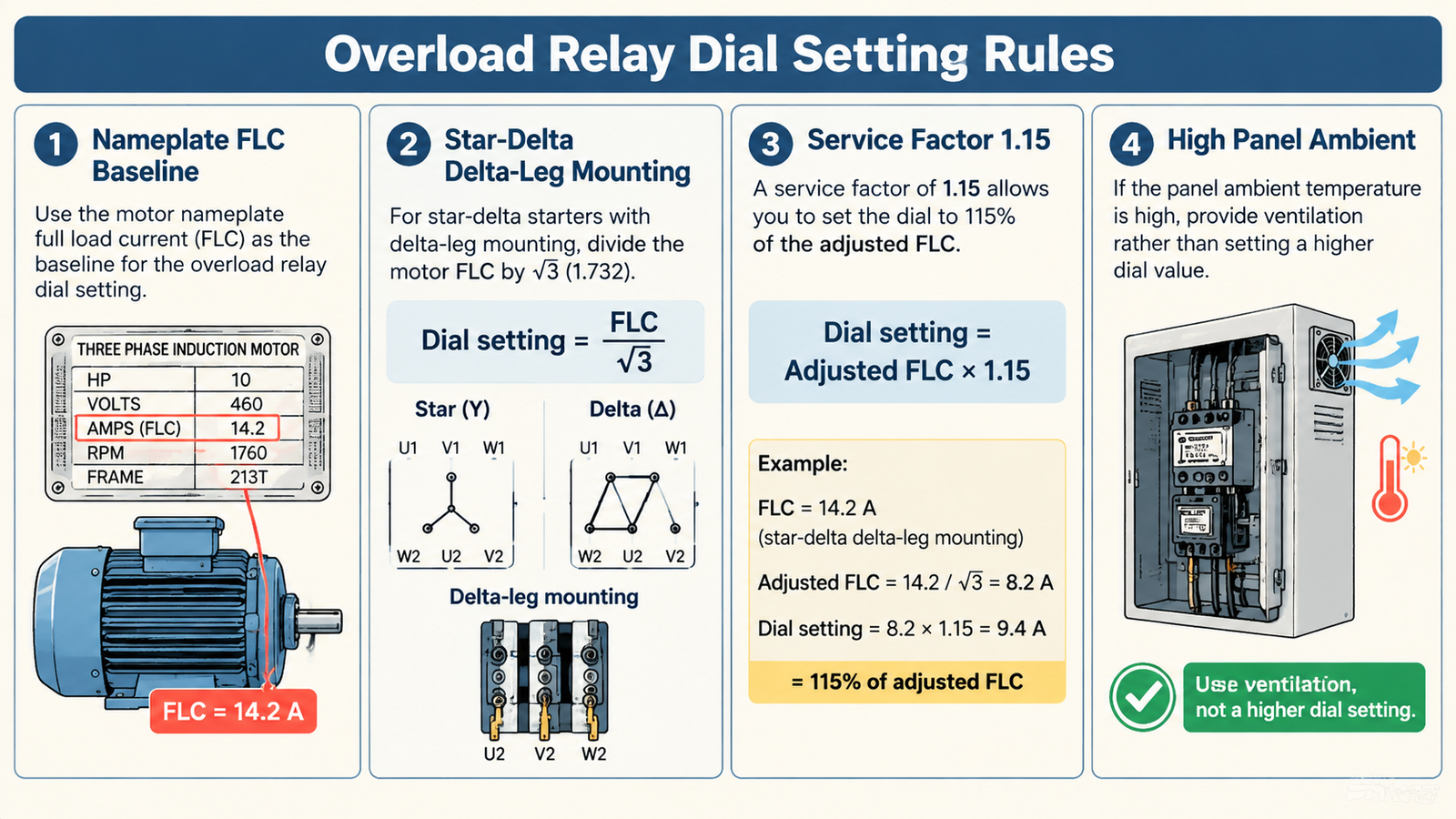
Set the dial to the motor’s nameplate full-load current for the actual supply voltage and connection. Do not set it to the current you measured with a clamp meter on a cool morning, and do not set it high “for margin”. The relay protects the winding, not the cable, so the winding’s rating is the only reference that matters.
Two adjustments sit on top of that baseline, and only two:
Everything else people do to the dial — nudging it up 10% because the relay tripped once in July, or matching the measured running current instead of the nameplate — removes protection and buys nothing.
The measured running current is a snapshot of one operating point: this valve position, this product on the conveyor, this ambient, this amount of impeller fouling. It moves. A dial set to a snapshot will trip a healthy motor the moment the operating point shifts, and it will under-protect the same motor when the load lightens and the setting stays high.
The nameplate current is a limit, not an observation. It is the current at which the winding reaches its rated temperature rise at rated conditions, and it stays true regardless of what the machine is doing today. That is why every credible setting procedure starts there.
There is one legitimate reason to look at measured current during commissioning: to confirm the motor is not already running above nameplate on day one. If a conveyor motor nameplated 29 A runs at 31 A on an empty belt, the problem is mechanical or the motor is undersized — not the relay setting.
A bimetallic relay trips on heat, and some of that heat comes from the panel rather than the current. Ambient compensation is a second bimetal element that offsets this, so the trip point stays close to the set value across a compensated range that is typically about −5 °C to +55 °C or +60 °C, depending on the family.
That range is the part people miss. A relay mounted above a drive, beside a braking resistor, or on the top row of a densely packed MCC in an unventilated room can sit well above the compensated band on a summer afternoon. Above the band, the trip point drifts down and the relay reads the motor as hotter than it is. The classic signature is a starter that trips only in hot weather, or only in the top row of a panel, with a current reading that is perfectly normal.
There are two correct fixes and one wrong one:
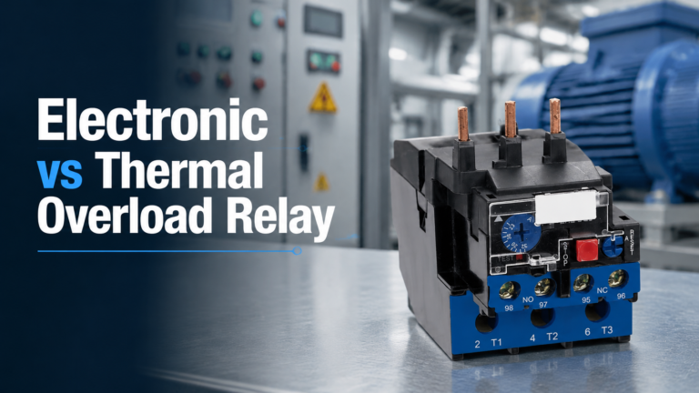
If the choice between the two technologies is still open, the accuracy and VFD-duty differences are covered in electronic vs thermal overload relay.
A bimetal element that has not fully cooled from the previous start begins the next one partway up its heating curve. Electronic relays reproduce this deliberately with a thermal memory that survives a power cycle. The result is a motor that starts fine cold, then trips on the second or third attempt within a short window.
That is the relay working correctly. The motor really is hotter than it was, and the winding does not care whether the heat came from one long overload or three quick starts. If the duty genuinely requires repeated starts, the answer is a higher trip class or a different starting method, not a higher dial.
The interaction between trip class and starting duty is the subject of NEMA Class 20 vs IEC Class 10; this article assumes the class is already appropriate and deals only with the current setting.
A trip is a measurement. Logged with the current reading at the time and the state of the machine, it is one of the cheapest wear indicators a plant has. A conveyor that ran at 26.5 A in March and trips at 28.9 A in September has not developed a relay problem — it has developed a bearing problem, and the relay found it before the bearing did.
This reframing changes the maintenance conversation. Instead of “the relay is oversensitive”, the record says “current has crept 9% since March”, which is an argument with a date on it.
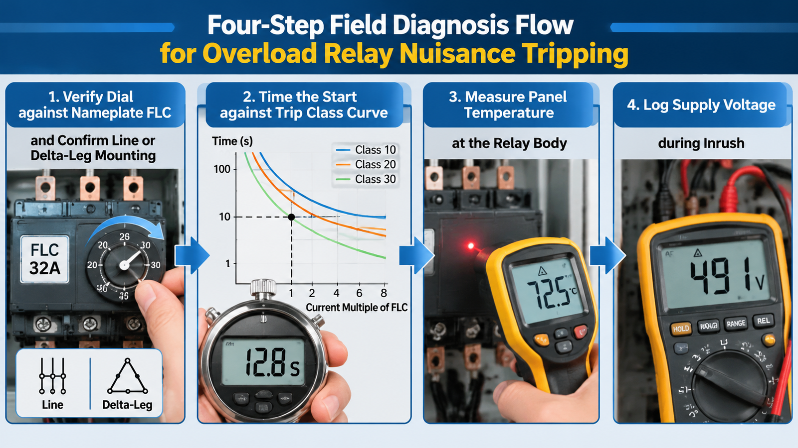
When a relay trips and nobody agrees why, work through these four checks in order. Each one is cheaper than the next, and the first is the most common cause by a wide margin.
| Step | What to check | What a fault looks like | Correct action |
|---|---|---|---|
| 1. Setting | Dial against nameplate FLC; confirm line or delta-leg mounting on star-delta starters | Dial set to measured current, or to FLC on a delta-leg relay | Reset to FLC (or FLC ÷ √3) |
| 2. Start time | Time from energise to full speed, compared with the trip class curve at the observed multiple of FLC | Start time inside or near the class window | Move up one trip class, keep the dial |
| 3. Panel temperature | Thermometer at the relay body during a hot-day trip | Above the compensated band (typically over 55–60 °C) | Ventilate, relocate, or use an electronic relay |
| 4. Supply voltage | Voltage during inrush; look for a 10–15% sag | Weak supply stretches run-up time at elevated current | Stagger starts, firm up the supply, or soft start |
If all four check out and the relay still trips, the load is genuinely heavier than the motor’s rating. That is a machine problem, and dialing it away converts a motor protection event into a rewind.
The table below is the practical version of everything above. It assumes a relay whose adjustable range covers the motor current, mounted in the starter, with the class already chosen for the starting duty.
| Condition | Dial position | Reason |
|---|---|---|
| Standard DOL motor, SF 1.0 | Nameplate FLC | Winding rated at that current, no margin available |
| Motor with service factor 1.15, margin genuinely used | Up to about 115% of FLC | Service factor defines usable continuous overload |
| Star-delta starter, relay in delta leg | FLC ÷ √3 | Relay carries phase current, not line current |
| Star-delta starter, relay on line side | FLC | Relay carries line current — confirm actual wiring first |
| Panel ambient above the compensated band | FLC, and fix the heat | Compensation has a ceiling; the dial is not the remedy |
| Repeated starts in a short window | FLC, with a higher trip class | Thermal memory is intentional; the class controls start tolerance |
Write these down at commissioning, on the panel schedule or in the machine file, and the next person to open the enclosure inherits your reasoning instead of guessing:
Five fields take about four minutes. They turn every future trip into a comparison rather than an investigation.
An overload relay does not clear short circuits and was never meant to. It integrates current over time and opens the contactor coil when the accumulated heat says the winding is in danger. Fault current is the job of the upstream breaker or fuses, and the two devices are a coordinated pair rather than alternatives.
When the starter also uses a breaker with motor-protection characteristics, the split of duties changes and the relay may become redundant. That trade-off is covered in thermal overload relay vs MPCB. For the internal construction that produces the bimetal response, see how a thermal overload relay works.
If you are commissioning a starter and want the relay and contactor supplied as a matched pair rather than sourced separately, the LC1-D series contactor range mounts the relay directly on the contactor body, which also removes a set of field wiring terminations from the panel.
Field setting is a short list of rules and a long list of temptations to break them. Set the dial to nameplate current for the actual connection, adjust for service factor only when the margin is real, correct star-delta mounting arithmetic, and treat heat, voltage sag and repeated starts as separate problems with separate fixes. Every trip you silence by turning the dial is a rewind you have scheduled for later.
Nameplate current for the actual supply voltage and connection. Measured current describes one operating point and changes with load, ambient and wear; a dial set to a snapshot will either trip a healthy motor or stop protecting it.
Panel temperature is above the relay’s ambient-compensated range, typically above 55–60 °C at the relay body. The trip point drifts down and the relay reads the motor as hotter than it is. Ventilate or relocate the relay, or use an electronic relay, rather than raising the dial.
Thermal memory. The bimetal element has not cooled from the previous start, so the second start begins partway up the heating curve. The relay is behaving correctly; if the duty requires repeated starts, choose a higher trip class or a different starting method.
If the relay is in the delta leg, set it to FLC ÷ √3 because it carries phase current. If it is wired on the line side, set it to FLC. Confirm which leg the relay is actually in before applying either number.
Only within the service-factor allowance, and only after the four-step diagnosis shows the setting was wrong. Raising the dial above the motor’s rating trades winding protection for quiet operation and is the most common cause of preventable motor rewinds.
No. Compensation holds the trip point steady within a defined band, roughly −5 °C to +55/60 °C. Above that band the correction runs out, which is exactly when nuisance trips appear in hot cabinets and top-row MCC starters.