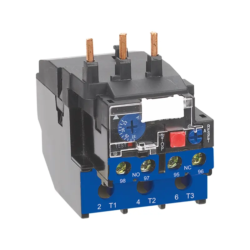
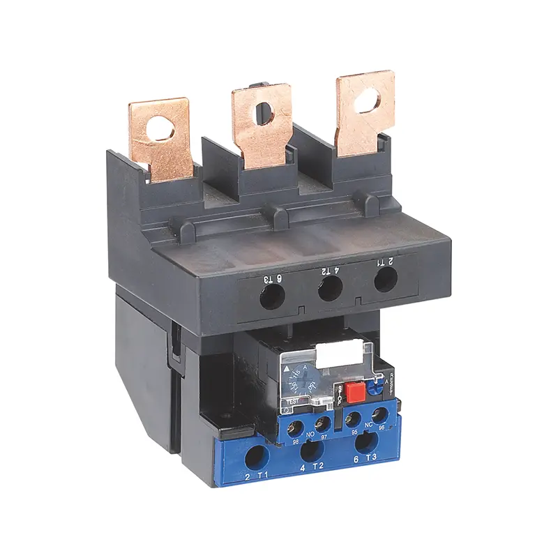
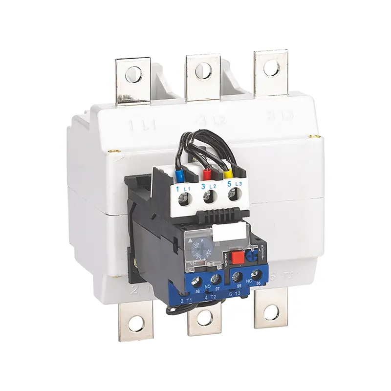
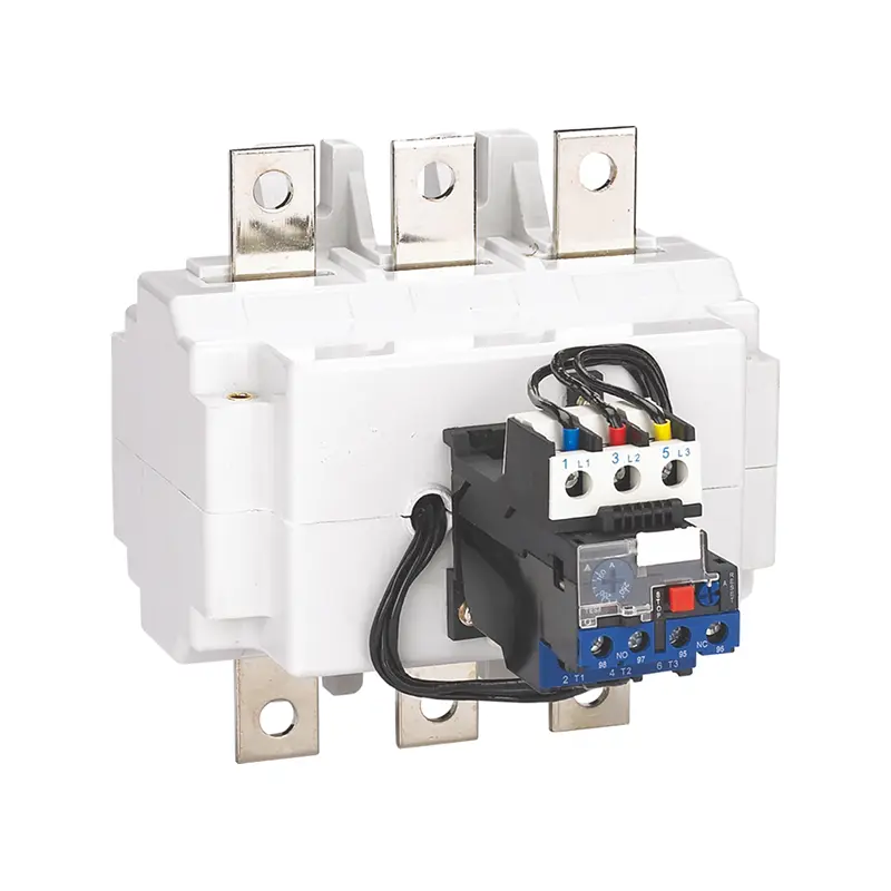
Description
CR2 Series Thermal Overload Relay
Anything that turns a shaft will eventually bind, block or run dry, and when it does the motor keeps drawing current while the work it was bought to do stops happening. The winding has no way to complain except by getting hot. A CR2 series thermal overload relay exists to notice that build-up early and open the motor circuit before the insulation is damaged — it is the sensing half of a starter, doing the job a contactor was never built for.
The series runs from 0.1 A to 630 A across seven frames, each holding a family of current bands so one dial span can be matched to a single motor’s load. The setting is continuously adjustable rather than stepped, the trip mechanism is temperature compensated, and the auxiliary contact is electrically separated from the main circuit. Trip figures and frame pairings are carried in the data table just above.
What the Relay Adds That the Contactor Cannot
A contactor makes and breaks a circuit on command; it has nothing with which to judge whether the current it passes is reasonable. That judgement needs a sensing element in series with the motor, which is why a starter is normally built as two parts — switching in one device, protection in the other.
Where the bimetal element comes in
Three bimetal strips carry the phase currents. Each is a sandwich of two metals expanding at different rates, so a sustained current above the setting bends it until the trip bar releases and the auxiliary contact opens. The delay is the point: a start-up surge passes through, while an overload lasting minutes heats the strip far enough to operate.
Why ambient compensation matters in a warm panel
Without compensation, a relay beside a hot transformer or in a sun-facing enclosure trips sooner than one in a cool cabinet, because its bimetal already starts warm. Compensation removes the ambient part from the decision, so the trip point follows motor current rather than board temperature.
Reading a CR2 Part Number
The catalogue reference states the family, the frame, and which current band inside that frame the unit is set up for — a few seconds of reading that is cheaper than returning a relay of the right family in the wrong range.
- CR2Family code — this thermal overload relay range.
- 33 (before the current code)Frame size — which of the seven frame bodies the relay is built in, and therefore which current bands are available in it.
- 57 (after it)Current rating code. Not the current itself, but a code mapping to one band, quoted against rated operational current at 380/400 V, AC-3 duty.
So CR2-3357 is CR2 family, frame 33, current code 57 — resolved on this page to 37–50 A, a 63 A aM fuse and a CC1-40 to CC1-95 contactor. Two frames can cover the same band, so both the frame digits and the current code matter.
Trip Times the Relay Has to Meet
Type-test figures show what a thermal overload relay will actually do, since each line states a current multiple and its time window. The overload and phase-failure elements work to separate published sets.
Read the first row of each set as a promise not to trip: a motor a few percent above setting is not a fault, and the relay must tolerate it for two hours from cold. The 2-to-10-second window at 7.2 times setting is what keeps a hard overload from becoming a short-circuit duty. The phase-failure element covers the asymmetric case where one phase drops out and the remaining two carry the whole load.
Balanced overload and phase failure
- 1.05 × setting — no trip within 2 hours, from cold
- 1.2 × setting — trip within 2 hours, from hot
- 1.5 × setting — trip within 2 minutes, from hot
- 7.2 × setting — trip between 2 and 10 seconds, from cold
- Two phases at 1.0, third at 0.9 — no trip within 2 hours, from cold
- Two phases at 1.15, third broken — trip within 2 hours, from hot
Which Contactor Each Frame Mounts To
A thermal overload relay is not chosen alone. It clips onto the load side of a contactor, or is wired alongside one, and the pair must carry the motor current together. The pairing runs by frame, and each frame brings its own set of current bands and a backup fuse rating for every band.
The seven frames pair with the CC1 contactor range as follows: CR2-03 with CC1-09K and CC1-12K; CR2-13 with CC1-09 up to CC1-32; CR2-23 with CC1-32; CR2-33 with CC1-40 up to CC1-95; CR2-43 with CC1-115 and CC1-150; CR2-53 with CC1-115 up to CC1-225; and CR2-63 with CC1-185 up to CC1-630. The band-by-band current, aM fuse and gG fuse figures for all seven frames sit in the attributes table above.
An aM rating is a motor-duty fuse, sized for the start inrush and meant to sit behind the relay rather than protect it; a gG rating is the general-purpose figure to quote when the backup device is an installation fuse. RT16 is recommended throughout. The frames overlap — the 23–32 A band appears in both CR2-23 and CR2-33 — so the choice turns on the contactor the panel already uses; give us that rating together with the contactor you are standardising on, and the pairing can be confirmed before the order is placed.
Setting the Dial, and What the Trip Class Costs You
Within its band the dial of this thermal overload relay turns continuously, so the setting is a real adjustment, not a pick between fixed steps. Dial in the full-load current printed on the motor’s own rating plate, run the machine under normal load, read the actual current and trim if the motor consistently works below rating. Trip class states how quickly the relay must operate at six times its set current; class 10 is the general-purpose bracket for most pumps, fans and machine drives, and a high-inertia fan may need a longer one. The class is fixed at build, so it belongs in the enquiry.
Controls and Terminals on the Front Face
Everything an electrician needs sits on the face: the setting dial, a tripping indicator, a test button for checking the mechanism off load, a stop button for manual breaking, and a reset selector left on manual for fault-finding or automatic so the machine restarts on the next command. On a multi-motor panel that saves a walk round every starter to find the one that dropped out. The auxiliary contact is a changeover pair, one normally open and one normally closed, electrically separated from the main circuit so it can sit at a different potential from the motor supply; its rated currents at 220 V and 380 V AC and at 220 V DC head the attribute list above.
Machines and Installations the Relay Belongs In
A three-phase motor with a contactor ahead of it is the plain case; the relay turns that pair into a starter. It suits installations where motors run unattended and a burnt winding is expensive:
- Pump sets, booster stations and borehole pumps
- Fans, blowers and air handling units
- Compressors and refrigeration drives
- Conveyors, mixers and agitators
- Machine tools and production line drives
- Cranes, hoists and material handling equipment
- Packaging, textile and food processing machinery
Panel builders and distributors keep it beside the switching devices it works with, so a starter can be assembled from one line. The AC contactor category carries the matching CC1 family, and the wider motor control and protection range groups the rest of the assembly. Where one compact device is preferred over a contactor-and-relay pair, a manual motor starter puts overload and short-circuit protection in one body on a three-phase motor circuit; where the load is switched from a control signal rather than by hand, a modular contactor is often the partner device in the same board.
Ordering Details and Own-Label Supply
Four decisions carry most of the risk on a thermal overload relay order: the frame and current band that suit the motor’s load; the trip class that suits its starting duty; the mounting style that fits how the starter will be built; and the auxiliary contact arrangement the control circuit expects. Settle those four and the ordering is routine; leave one open and the wrong relay arrives.
Own-brand marking from your artwork, packing to your own design and documentation drawn up for the market you are shipping into are all available under OEM and ODM arrangements, and mixed pallets can be built so one shipment carries a distributor’s full spread of frames and current bands. Goods ship from China, and packing method, delivery timing and the branding options open at your volume are confirmed in the quotation. Send the frames, quantities and port of discharge, and the pricing can be worked out. Contact us for CR2 thermal overload relay price, technical specifications, datasheet, bulk quantity, and OEM supply information.
FAQ
What does a thermal overload relay actually protect?
It protects the motor winding, the cable feeding it and the contactor that switches it. A sustained current above the setting heats three bimetal strips until they bend far enough to open the auxiliary contact and drop the contactor coil. It does not protect against short circuit, and it does not protect people against electric shock.
How do I pick the right frame and current band for my motor?
Start from the full-load current on the motor nameplate, then choose the frame whose band contains it. Because bands overlap at the edges of adjacent frames, a borderline motor can usually be served by either of two frames, and the deciding factors are the matching contactor and the way the starter will be assembled. Share the motor's rating plate details with your enquiry and we can confirm the combination.
How does the CR2 decide it has to trip, and how long does it take?
Three bimetal strips sit in series with the motor phases and bend as they heat. At 1.05 times the setting the relay must hold for two hours from cold, so a small margin above nameplate is tolerated; at 1.2 times it trips within two hours from hot, at 1.5 times within two minutes, and at 7.2 times between two and ten seconds from cold. A separate phase-failure element trips within two hours when one phase is broken while the other two sit at 1.15 times setting.
Can this relay be used on its own, without a contactor?
Not for motor duty. The relay senses current and opens its auxiliary contact, but that contact is a control signal rather than a load-carrying break. Something has to interrupt the motor circuit itself, and in a motor starter that job belongs to the contactor the relay is plugged onto or wired alongside.
How is it different from a motor protection circuit breaker?
Both sense overload, but they sit in different places. A combined starter device puts overload and short-circuit sensing together with manual switching in one compact body, and is often used on a single motor circuit. An overload relay is the protection element of a contactor-based starter, so it adds overload duty to an assembly that already includes a contactor and separate short-circuit protection.
Can the CR2 relay be supplied under our own brand?
Yes. Own-label marking from your artwork, packaging to your specification and documentation prepared for the market you are shipping into are all available under OEM and ODM arrangements. Mixed pallets and containers can also be assembled so a single shipment covers a distributor's full spread of frames and current bands.
Request Quote
Tell us your specifications, quantity, or application scenario and we will reply with a tailored quote.