DC Contactor Selection for 600 V and 1000 V Systems
DC has no zero crossing, so voltage rating, time constant and pole configuration decide everything. A five-step selection for BESS, PV and EV charging.
Read More
Every number on a contactor’s nameplate — the AC-3 current, the 85–110 % coil band, the making capacity, the trip class shared with its overload relay — comes from one document: IEC 60947-4-1, Low-voltage switchgear and controlgear — Part 4-1: Contactors and motor-starters. Buyers and panel designers cite the standard constantly but rarely see how it is organized, so this page maps the standard clause by clause: what each requirement covers, which test proves it, and what to demand in a manufacturer’s test report.
The 60947 series partitions low-voltage switchgear by device family, and the boundaries matter when you read a datasheet:
| Standard | Covers | Not covered by it |
|---|---|---|
| IEC 60947-4-1 | Electromagnetic contactors, motor starters (contactor + overload relay combination), AC and DC | Circuit breakers, auxiliary contact blocks as separate devices |
| IEC 60947-2 | Circuit breakers (MCCB/ACB) — the SCPD partner | Contactors and starters |
| IEC 60947-5-1 | Control circuit devices and switching elements — including auxiliary contacts of contactors | Main (power) contacts |
| IEC 60269 | Fuses — the other common SCPD | — |
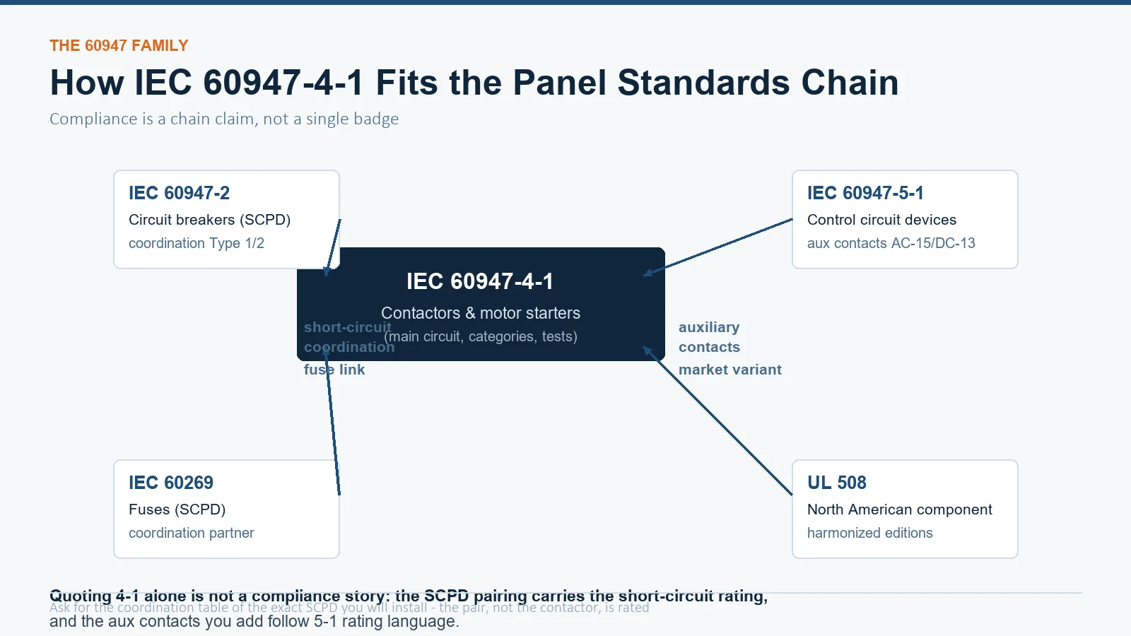
Two consequences follow. First, the auxiliary contacts you buy as add-on blocks are rated under 60947-5-1, not 60947-4-1 — the rating language difference (AC-15/DC-13 vs AC-1..AC-4) is decoded in auxiliary contact vs main contact. Second, “coordinated short-circuit protection” is a joint claim between a contactor (4-1) and its SCPD (4-2 or 60269), tested as a pair.
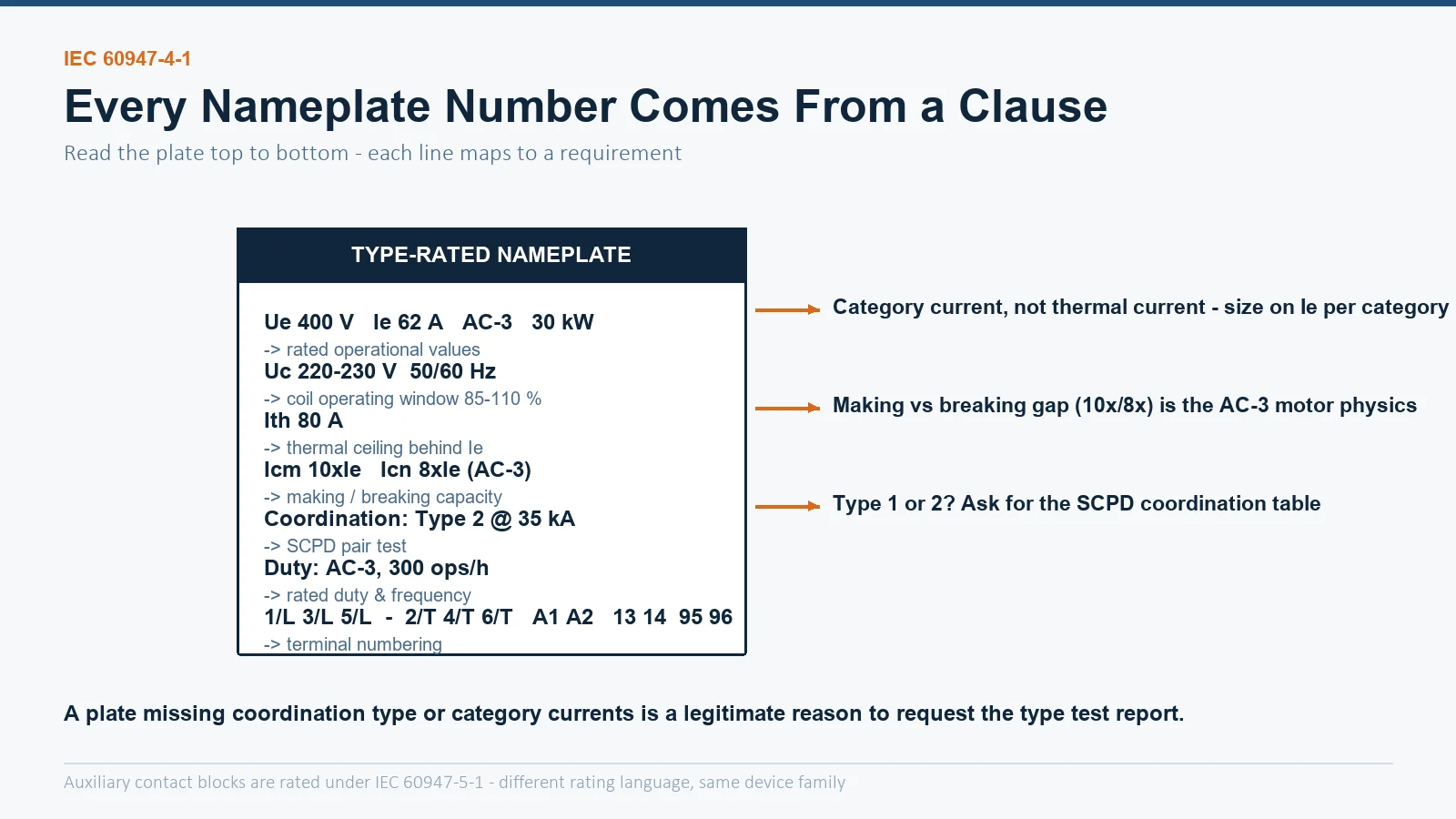
| Nameplate marking | What it means | Where it comes from |
|---|---|---|
| Ue 380/400/660 V, Ie …A | Rated operational voltage and current, per utilization category | Rated characteristics clause |
| AC-3: 30 kW | Operational current for squirrel-cage motor duty at that voltage | Utilization category tables |
| Uc 220/230 V 50/60 Hz | Rated control circuit voltage and frequency | Coil operating limits: 85–110 % pickup, 20–75 % drop-out |
| Ith / rated thermal current | Free-air thermal current — the ceiling behind Ie | Rated characteristics clause |
| Icm / making capacity | Peak current the contacts must close against (e.g. 10× Ie for AC-3) | Making and breaking capacity requirements |
| Icn / breaking capacity | Current the contacts must break (e.g. 8× Ie for AC-3) | Making and breaking capacity requirements |
| Type “1” or “2” coordination | Short-circuit behavior with the declared SCPD | Coordinated short-circuit protection test |
| Duty: AC-3, 300 ops/h | Rated duty with operating frequency | Duty and operating frequency clauses |
The category system (AC-1 to AC-4, DC-1 to DC-5) converts “what load are you switching” into testable making/breaking requirements and endurance expectations. The full table with cosφ values and typical applications lives in AC-1 to AC-4 utilization categories explained; the selection math built on it is in how to size and select a contactor. What matters at standard level: the category is not decoration — it defines which making/breaking test the contactor passed and how much electrical endurance you may expect. An AC-3 rating says nothing about how the device behaves plugging a motor; that is AC-4, and the same physical frame carries a much smaller AC-4 current.
| Category | Making capacity | Breaking capacity | Power factor (cosφ) |
|---|---|---|---|
| AC-1 | 1.5 × Ie | 1.5 × Ie | 0.95 |
| AC-2 | 4 × Ie | 4 × Ie | 0.65 |
| AC-3 | 10 × Ie (8 × Ie above 100 A) | 8 × Ie (6 × Ie above 100 A) | 0.65 up to 17 A; 0.35 above |
| AC-4 | 12 × Ie (10 × Ie above 100 A) | 10 × Ie (8 × Ie above 100 A) | 0.65 up to 17 A; 0.35 above |
The AC-3 asymmetry is the tell of a real motor duty: closing against a motor at standstill means inrush (up to 10× — the making test), while a normal break happens at running current near synchronous speed (8× — the breaking test). AC-4 breaks at reduced speed with the rotor still drawing starting current, hence the higher symmetric figures. Note these are occasional-operation type test values — the standard also defines separate conditions for the endurance tests (AC-3 makes at 6×, breaks at 1× per normal stop), which is why a contactor that starts a motor a thousand times is doing far gentler work per operation than one that plugs it a hundred times.
The standard’s test sequences are the reason two contactors with identical nameplates can behave completely differently in a fault. The main type tests:
| Test | What it proves |
|---|---|
| Temperature-rise test | Terminals and coils stay within limits at rated thermal current |
| Operating (characteristic) limits | Pickup 85–110 % Uc, drop-out 20–75 % Uc, timing within class |
| Dielectric properties | Insulation withstands impulse and power-frequency test voltages |
| Making/breaking capacity | The category table values, at specified cosφ and sequences |
| Coordinated short-circuit test | Contactor + SCPD pair behaves as Type 1 (no hazard outside, may need repair) or Type 2 (no weld, operable) at declared Icc |
| Endurance tests | Mechanical (no-load) and electrical (loaded) operations to declared life |
Type 1 vs Type 2 is the distinction buyers should understand before comparing prices: a Type 2 rating at your prospective short-circuit current means the contactor survives the fault without welding and remains serviceable — a genuinely harder test, covered from the application side in contactor vs circuit breaker: switching duty vs protection.
A nameplate missing the coordination type or the category currents is a legitimate reason to ask for the type test report — serious manufacturers publish or provide it on request, and the audit questions worth asking are listed in manufacturer or trader: how to vet a supplier.
In a real panel the contactor sits inside a chain of standards, and quoting 4-1 alone is not a compliance story:
| Document | Why you ask |
|---|---|
| Type test report (making/breaking, endurance, temperature rise, dielectric) | Proves the nameplate is measured, not estimated |
| Coordination table for your SCPD and fault level | Type 1/2 claim at the current your panel actually sees |
| Electrical endurance curves per category | Maintenance planning from real data, not the brochure number |
| Routine test certificate per delivery lot | Dielectric and operating checks applied to the units you buy |
| Declaration of conformity (CE/UKCA/CCC as applicable) | Chain of responsibility beyond the datasheet |
It is the IEC standard defining the ratings, characteristics, tests and markings for contactors and motor starters — the document behind every number on a contactor nameplate.
4-1 covers contactors and motor starters (main power circuit); 5-1 covers control circuit devices including the auxiliary contact blocks fitted to or alongside the contactor, with their own rating language (AC-15/DC-13) and requirements.
Because a motor start closes against up to 10× inrush current, while a normal break happens at running current — the standard reflects the physics of each event: 10× making, 8× breaking for AC-3.
That the contactor plus its short-circuit protective device has been tested so that, at the declared fault current, no contact welding or damage prevents the starter being put back in service — only the SCPD may need attention. Type 1 merely guarantees safety with possible contactor damage.
Yes — the standard covers DC utilization categories DC-1 to DC-5 with the same structure of ratings, making/breaking requirements and verification tests, using time constants instead of power factor.
No. The standard is the product requirement; CE marking is the manufacturer’s declaration that applicable directives are met, using standards like 60947-4-1 as the accepted route. Ask for both the declaration and the type test evidence behind it.
Buying to spec, not to nameplate? The CJX2-F series AC contactors are manufactured and tested to IEC 60947-4-1 with type test documentation, coordination tables and full marking compliance available on request — send us your project specification and we will quote with the paperwork attached.