What’s The Real Difference Of AC Contactor And Relay?
Published: Author: Wilmall
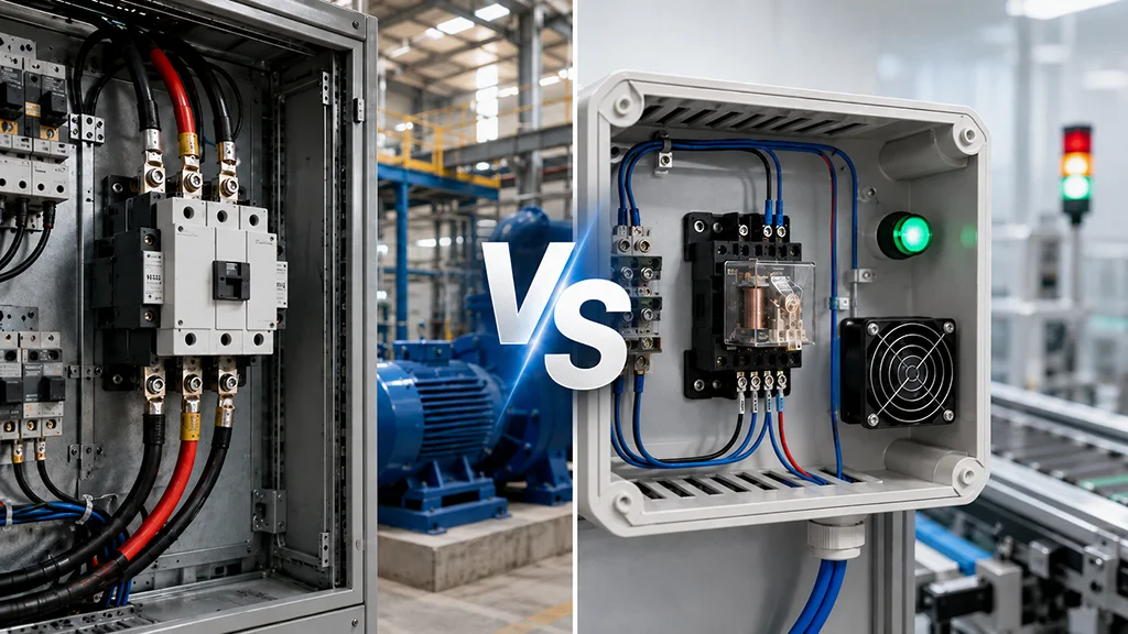
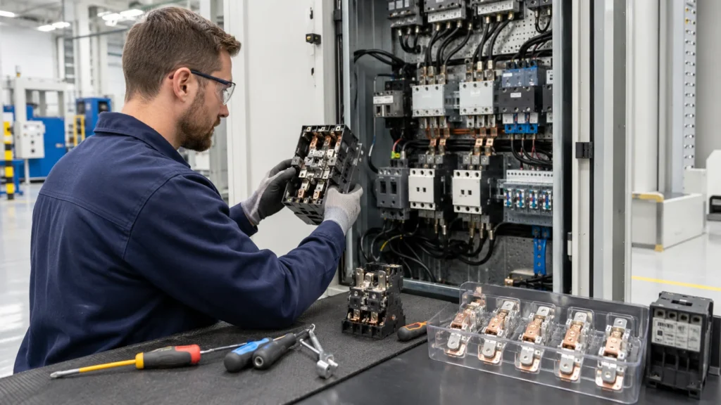
AC Contactor and Relay have difference? Walk into any electrical panel, and you’ll spot both contactors and relays sitting side by side. They look similar enough to fool a casual observer — both are rectangular boxes with terminals, coils, and moving contacts inside.
Put a CJX2-F225 AC contactor next to a standard industrial relay, and at a distance, you’d have a hard time telling which is which.
That’s where the confusion starts. An electrician once told me he spent half a morning troubleshooting a pump system, only to realize the panel builder had swapped in a relay where a contactor belonged.
The relay worked fine on the bench test but burned its contacts within two weeks once the 15 kW motor started pulling current.
So here’s the thing: wilmall contactors and relays do share the same working principle. Voltage hits the coil, magnetic field pulls the armature, and contacts close.
But the engineering decisions behind them — the contact materials, the arc quenching design, the mechanical stiffness — diverge sharply once you cross the roughly 10-amp threshold.
This article lays out those differences in plain terms, with clear guidelines on when each one belongs in your circuit.
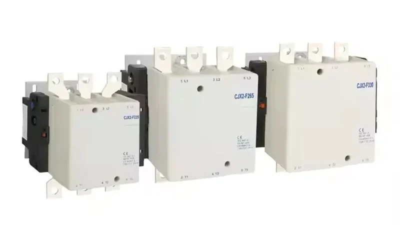
AnAC contactor is a heavy-duty electromagnetic switch built to handle power circuits — think motor starters feeding 7.5 kW, 22 kW, or even 160 kW machines.
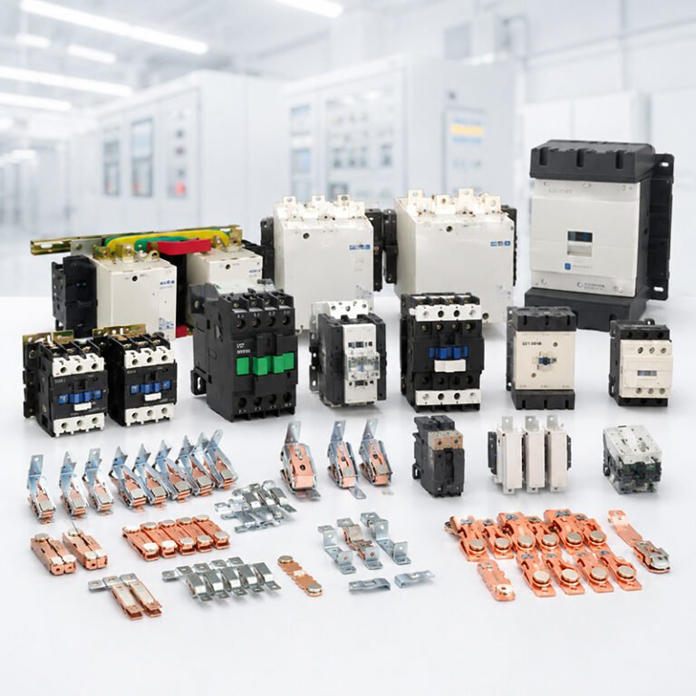
Les CJX2-F series from Wilmall, for instance, spans from 115A all the way to 800A rated operational current. These aren’t signal-level devices. They live on DIN rails inside noisy motor control centers, where they switch three-phase 380V or 660V power hundreds of times a day.
What makes a contactor a contactor? Three things: the contact tips are often made of silver-cadmium oxide (AgCdO) or silver-tin oxide (AgSnO2) alloys that resist welding;
The arc chutes (or arc grids) are built-in and sized for real fault currents; and the mechanical structure is rigid enough to handle 1 to 10 million operations.
Relay
A relay performs the same basic trick — electromagnetic coil, moving armature, set of contacts — but it’s designed for control circuits, not power circuits. Relays typically switch currents in the 2A to 16A range, at 24V DC or 230V AC.
They’re found in PLC cabinets, logic interlocking circuits, and signal isolation applications where the goal is passing a control command, not energizing a motor.
Most relays use contacts with thin silver or gold plating optimized for low contact resistance at small currents. Arc suppression, if present at all, is minimal — a small magnet or a plastic partition.
The coil itself draws maybe 1-3 VA, compared to 100-500 VA for a large contactor’s coil holding power.
Core Differences at a Glance
The table below captures what separates these two devices. It’s not just about bigger current numbers — the design philosophy changes completely once you cross into contactor territory.
Paramètres
AC Contactor
Relay
Rated Current
9A – 800A+
2A – 16A
Typical Voltage
220V / 380V / 660V AC (3-phase)
12V / 24V DC; 230V AC (1-phase)
Primary Circuit
Power circuit (motor, heater, lighting)
Control circuit (PLC I/O, interlock logic)
Contact Material
AgCdO, AgSnO2 (arc-resistant)
AgNi, Ag, Au-plated (low resistivity)
Arc Suppression
Built-in arc chutes / magnetic blowout
Minimal or none
Mechanical Life
5 – 10 million cycles
10 – 100 million cycles
Electrical Life (AC-3)
600,000 – 1,200,000 cycles
100,000 – 500,000 cycles
Coil Power
5 – 500 VA
0.5 – 3 VA
Physical Size
Compact to very large (palm-sized to shoebox)
Small (matchbox to credit-card sized)
Auxiliary Contacts
Often built-in + expandable
Built-in, usually 1-4 poles
The numbers tell a clear story. A CJX2-F225 contactor rated at 225A AC-3 will shrug off an 8x inrush that would instantly weld a relay’s contacts shut.
Meanwhile, a relay with gold-plated contacts will reliably switch a 50 mA PLC input signal — something a contactor’s heavy AgCdO contacts would struggle with because the oxide film needs a minimum “wetting current” to break through.
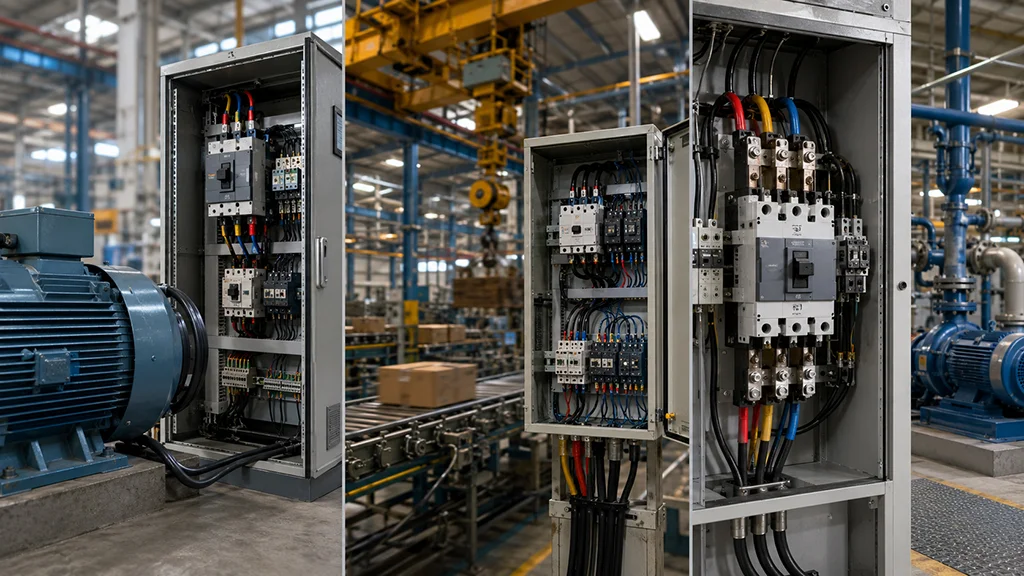
When to Choose an AC Contactor
Here’s the rule of thumb I’ve seen on countless sites: if the load has a motor nameplate on it, use a contactor. That’s not 100% precise, but it’s right more often than not. Let me break it down into real scenarios.
Motor Starting and Control
This is the contactor’s bread and butter. When a 30 kW induction motor starts DOL (Direct On-Line), the inrush current hits 6 to 8 times the full-load rating.
That’s easily 350-400A briefly — way past what any relay can survive repeatedly.
Contactors rated for AC-3 utilization category are specifically designed for this duty.
The Wilmall CJX2-F series covers exactly these scenarios, from the F115 for smaller 55 kW motors up to the F630 and beyond for 315 kW machines.
High-Frequency Switching
Crane hoists, conveyor belts, and production-line machines often cycle on and off every few seconds.
A relay’s contacts simply can’t take that kind of punishment.
Contactors like the CJX2-F400 mechanical interlocking contactor are built with thicker silver-alloy tips that trade a slightly higher contact resistance for dramatically better arc erosion resistance.
At 3,600 operations per hour, that difference means a contactor runs for years while a relay would fail in weeks.
Multi-Pole Power Switching
Three-phase loads need simultaneous switching of all three phases.
Les CIX2-D170 handles 170A across all three poles with a single coil — drop one phase late or early and you’ll get voltage imbalance that can damage the motor.
Relays can’t guarantee that kind of synchronized switching at power levels.
Now, relays aren’t the “weaker sibling.” They do things contactors can’t.
Wiring an LC1-D40 contactor’s coil straight to a sensitive PLC output is a fast way to fry the transistor — the coil inrush alone can exceed 100 VA, while most PLC outputs top out at 0.5A at 24V DC.
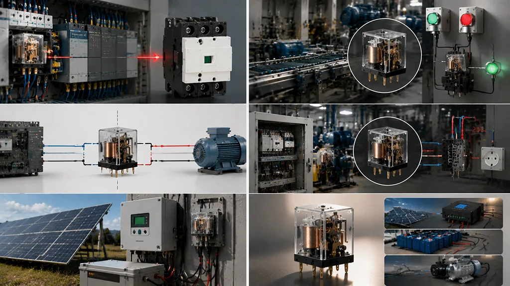
Logic Control and Interlocking
This is relay territory.
When you need to implement a start/stop latch, a safety interlock, or a sequence timer between sensors and actuators, relays with gold-flashed bifurcated contacts are your friend.
They’ll reliably switch millivolt-level signals from proximity sensors without contact bounce corrupting the logic.
Signal Isolation
Many industrial systems use relays for galvanic isolation between different voltage domains.
A 24V DC control panel talks to a 230V AC circuit through a relay’s coil-to-contact isolation barrier.
That’s a job contactors don’t compete for — they’re too expensive and too large for this role.
Low-Power DC Loads
Solar charge controllers, battery management systems, and small DC pumps all fall in the relay’s sweet spot.
Switching 48V at 15A DC is exactly what industrial relays are rated for, and doing it with a contactor would be overkill — physically, electrically, and cost-wise.
Can You Swap One for the Other?
The short answer: don’t. But here’s what happens if you try.
Relay in place of a contactor:
The contacts will weld on the first or second motor start. The arc from a 15 kW motor’s inrush current blasts right through the thin silver layer, and once the base metal underneath starts pitting, contact resistance spirals upward.
Heat builds, the plastic housing deforms, and within days — sometimes hours — you’ll have a dead short or an open circuit. I’ve seen a 12A-rated relay literally catch fire inside a panel when someone used it for a 7.5 kW compressor.
Contactor in place of a relay:
Less dramatic but still problematic. The heavy AgCdO contacts need a minimum wetting current (roughly 10-20 mA) to maintain low contact resistance.
Below that, surface oxidation builds up and you’ll get intermittent open-circuit faults on signal lines. Not to mention a contactor draws 10-50 times more coil power, which might overload the driving circuit.
Safety and Installation Notes
Whether you choose a contactor or a relay, a few safety fundamentals apply to both.
IEC 60947 Compliance
AC contactors sold for industrial use in most markets should comply with IEC 60947-4-1, which defines the utilization categories (AC-1 through AC-7b).
This standard specifies switching capacity tests, temperature rise limits, and endurance requirements.
The Wilmall CJX2-D (LC1-D) series is built to this standard, which means the contactor has been tested to handle full rated current under AC-3 conditions through at least 6,000 operating cycles without contact welding or excessive temperature rise.
Coil Voltage Selection
Always match the coil voltage to your control circuit.
Wilmall contactors are available with 24V, 110V, 220V, and 380V coil options. Under-voltage causes chatter — the contacts bounce rapidly and arc repeatedly, destroying themselves in minutes.
Over-voltage overheats the coil and can burn it out within hours. Check the nameplate.
Arc Flash Protection
When a contactor interrupts a motor’s running current, the arc inside the chute reaches roughly 3,000°C for 10-15 milliseconds.
That’s normal — the arc chute is built to handle it. But it means you should never operate a contactor with the arc chute cover removed, and you should always verify proper clearances inside the panel per the manufacturer’s installation sheet.
For the CJX2-F630, for example, the recommended clearance above the arc chute vent is at least 30mm.
Thermal Considerations
Contactors generate heat — the coil draws continuous power while energized, and the main contacts have a small but real voltage drop (typically 50-100 mV at rated current).
Inside a sealed IP65 panel without ventilation, ambient temperature can easily climb 10-15°C above outside air.
Les 3TF series contactors from Wilmall are rated for 55°C ambient without derating, making them a good fit for enclosed installations.
Periodic Inspection
Check contactor contacts every 50,000-100,000 operations for signs of uneven wear, pitting, or material transfer.
When contacts need replacement, use manufacturer-specified kits — the Wilmall CJX2/CJX4/CJ35 replacement contact kits use the same silver-alloy formulations as the original parts.
Substituting generic contacts changes the arc behavior and can reduce electrical life by 50% or more.
The same logic applies to relays, though at their lighter duty cycle, inspection intervals can be much longer.
FAQ
What is the basic functional difference between a contactor and a relay?
A contactor and a relay are both electrically controlled switches, but a contactor is designed for high-current, high‑power circuit switching, while a relay is optimized for low‑power or control signal switching. Contactors are commonly used in motor and power applications, whereas relays are used in logic control or signal circuits.
Can I use a relay instead of an AC contactor for motor control?
No — for motor starting, frequent switching, and high current loads, a contactor is the correct choice. Relays cannot reliably handle the high inrush current and repeated mechanical load required for three‑phase motors and heavy industrial equipment.
Why are contactors better for heavy loads than relays?
Contactors are built with larger contacts, arc suppression features, and stronger coils so they can carry and interrupt high current and voltage loads safely and repeatedly. Relays lack the necessary arc control and contact design to withstand heavy inductive loads.
Where are relays still the best choice?
Relays excel in logic control, signal isolation, and low‑current applications such as PLC signal switching, interlock circuits, sensor feedback, or small DC/AC control circuits. They are compact, cost‑effective, and work well for light electrical loads.
Which device is more durable for frequent switching?
For frequent on/off operations under heavy load, contactors are more durable due to their mechanical and electrical design. Relays can switch frequently only at lower loads; at high loads they wear quickly. Contactors are built to operate millions of cycles even under industrial duty.
Imagine your factory’s electrical distribution system as a complex railway network. Trains (electric current) need signals to know when to proceed. The AC contactor acts as the signal controller—receiving commands from operators or automation systems and determining when power flows to motors, heaters, and other industrial equipment. This electromagnetic switch performs millions of operations over […]