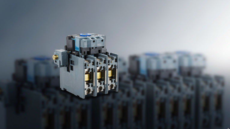
Auxiliary Contact vs Main Power Contact Key Differences in a Contactor
Published: Author: Lisa
If you have ever stood in front of a contactor and wondered why one set of terminals is labeled 1/L1 and 2/T1 while another small pair is labeled 13-14, you are looking at the difference between main contacts and auxiliary contacts. The Main Power Contact switches the load current that actually runs the motor, heater, or lighting circuit. The auxiliary contact switches nothing but control information: feedback, interlocks, indicator lamps, and PLC inputs.
They move together inside the same housing, but they are built, rated, and standardized for completely different jobs. This guide compares auxiliary contact vs main contact side by side, using the real ratings of an industrial frame so you can see exactly how wide the gap is. If you are selecting or cross-referencing AC contactors, this distinction decides both what you order and how you wire the panel around it.
Main Power Contacts Switch Power, Auxiliary Contacts Switch Signals
Main contacts switch the load current. Auxiliary contacts switch control signals. Everything else follows from that one sentence.
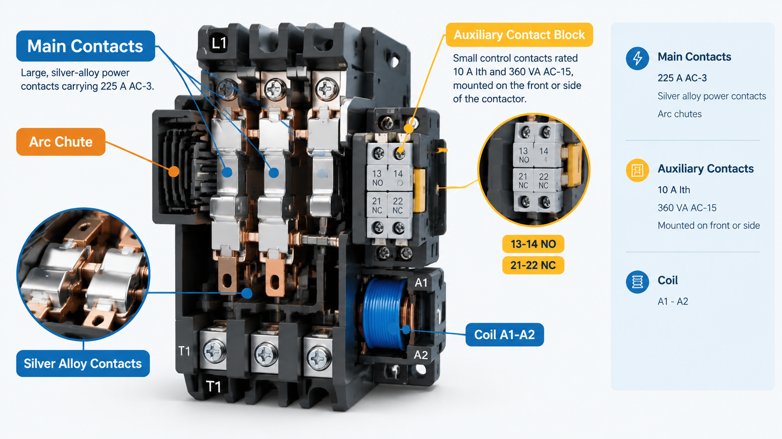
Main contacts connect the supply to the load. On a three-pole contactor they are the large terminals marked 1/L1 to 2/T1, 3/L2 to 4/T2, and 5/L3 to 6/T3, and they are sized, material-selected, and arc-managed for tens or hundreds of amps. Auxiliary contacts are the small contact pairs mounted on the front or side of the same contactor. They change state at the same moment as the main contacts, but their only job is to tell the control circuit what happened.
Aspect
Main Power Contacts
Auxiliary Contact
Primary function
Switch the load circuit
Signal and control the control circuit
Typical current
9 A to 800 A depending on frame
Typically 10 A thermal; far less at AC-15/DC-13
Typical terminals
1/L1–2/T1, 3/L2–4/T2, 5/L3–6/T3
13-14 (NO), 21-22 (NC), 31-32, 43-44
Governing standard
IEC 60947-4-1 (contactors and motor starters)
IEC 60947-5-1 (control circuit devices)
Utilization categories
AC-1, AC-2, AC-3, AC-4
AC-15, DC-13
Contact system
Large silver-alloy contacts with arc chutes
Small signal contacts, often without a dedicated arc chute
Can it replace the other?
No
No
One memory aid covers most of what follows: main contacts control power, auxiliary contacts control information.
What Are the Main Power Contacts?
A Main Power Contact is the power-switching contact inside a contactor. When the coil energizes, the armature pulls the movable contact bridges against the fixed contacts and the load circuit closes. When the coil drops out, springs pull the bridge back and the circuit opens. Because the main contact interrupts inductive load current, it must survive an arc on every operation, which is why main contacts sit inside arc chutes and use large masses of silver-based alloys.
Main contacts are always normally open. A contactor is a remote-controlled switch, so in the rest state (coil de-energized) the power circuit is open. There is no “normally closed” main pole on a standard contactor; if your circuit needs the load energized at rest, that is a design problem to solve with the control circuit, not with the contactor.
How Main Contacts Are Rated
Main contacts are rated by utilization category, and the category matters more than the ampere number alone. An AC-1 resistive duty and an AC-3 motor duty stress the same contact in very different ways, which is why AC-1 to AC-4 utilization categories exist as separate ratings on the same frame. A contactor that is fine on an AC-1 heater bank can fail in months on AC-4 plugging duty at the same current. If you are new to terminal markings on the power side, our guide to what L1, L2, T1 and T2 mean on a contactor walks through the line-side and load-side convention in detail.
What Are the Auxiliary Control Contacts?
An auxiliary contact is a mechanically operated control contact that changes state when the contactor changes state, but which sits electrically in the control circuit, not the power circuit. It is built as a small contact pair, usually rated in single-digit amps, and it exists for one reason: so that the rest of the control system can know and react to what the contactor is doing.
Auxiliary contacts come in two polarities:
Normally open (NO): open at rest, closes when the coil energizes. Used for seal-in circuits, run indication, and “contactor is on” feedback to a PLC.
Normally closed (NC): closed at rest, opens when the coil energizes. Used for interlocks, stop permissives, and opposite-state indication.
Most industrial frames ship with a small number of built-in auxiliary contacts and accept snap-on auxiliary contact blocks to add more. That is the practical answer to the common question “can I add auxiliary contacts to an existing contactor?” — yes, as long as the block is the correct accessory for that contactor series, because the operating mechanism and travel are matched by the manufacturer.
How Auxiliary Contacts Are Rated: AC-15 and DC-13
Here is where most specifications go wrong. An auxiliary contact does not have one current rating; it has several, and they are not interchangeable. Because auxiliary contacts switch control loads — coils, solenoids, PLC inputs — they are evaluated under IEC 60947-5-1 using the control-circuit utilization categories:
AC-15: switching AC electromagnetic loads such as contactor and relay coils. Inductive, so the rating is expressed in volt-amperes (VA).
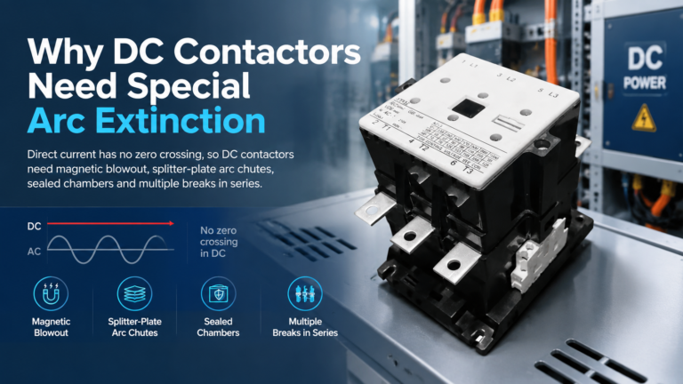
DC-13: switching DC electromagnetic loads. This is the hardest duty for a small contact, because a DC arc has no natural zero crossing to extinguish it, so the rating is expressed in watts (W) and is dramatically lower than the AC figure.
A datasheet that only says “1NO auxiliary contact” tells you almost nothing. What you actually need is the AC-15 rating in VA at your control voltage and the DC-13 rating in watts if the coil circuit is DC.
The Rating Gap, Quantified on One Real Frame
Abstract comparisons hide how extreme the difference is, so let us use one device and its published data. The CJX2-F225 is a 225 A three-pole industrial contactor whose series accepts auxiliary contact groups, air delay heads, mechanical interlocks, and thermal relays. Its main contacts and its auxiliary contacts are rated as follows:
パラメータ
Main Contacts
Auxiliary Contacts
Rated thermal current (Ith)
275 A
10 A
Rated operational current
225 A at AC-3, 380 V (85 A at AC-4)
≈0.95 A at AC-15, 380 V (360 VA)
DC control duty
Not applicable to this AC frame
33 W at DC-13 (≈0.15 A at 220 V DC)
Rated operational voltage
Up to 1,000 V (Ui 1,000 V)
380 V AC / 220 V DC
Load it actually switches
110 kW motor at 380 V AC-3
Coils, lamps, PLC inputs
Look at the middle rows. At the same 380 V, the main contacts make and break 225 A while the auxiliary contacts handle roughly 0.95 A — a ratio of nearly 240 to 1. On the DC side the gap is even more brutal: a DC-13 rating of 33 W at 220 V works out to about 0.15 A, roughly 1,500 times less than the AC-3 main current. This is not a design margin you can borrow. The auxiliary contact is a different physical contact system with a different contact mass, different materials, and no arc chute sized for load current.
The practical rule that falls out of this table: if the wire you are about to land on the terminal also feeds a motor, a heater, or a lighting load, it belongs on a main contact. If the wire comes from a PLC input, an indicator lamp, or another contactor’s coil, it belongs on an auxiliary contact. For a worked example of how a frame like this is selected around its main contacts, see our guide on contactors for motor starters.
How to Read Contactor Terminal Numbers
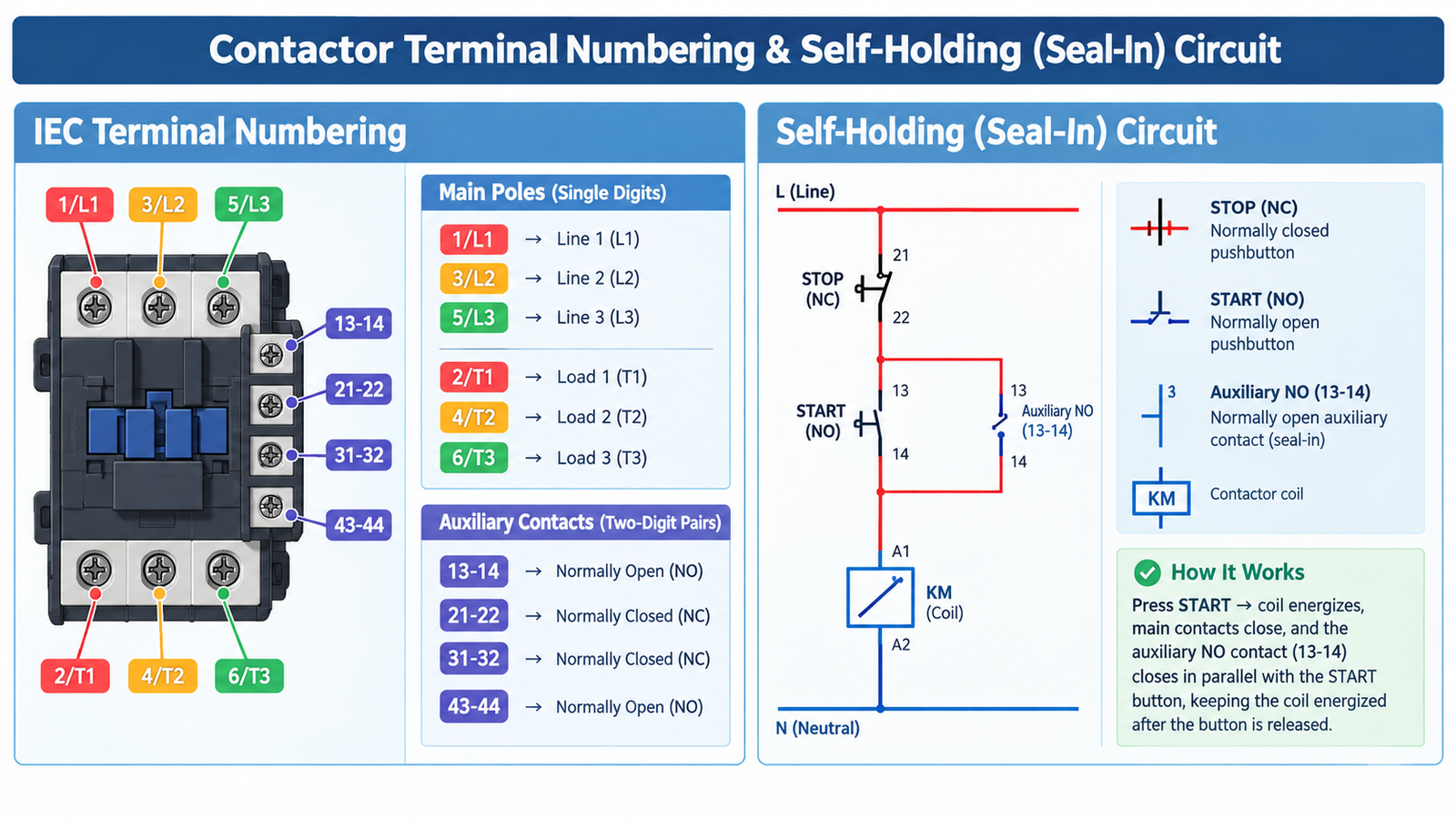
The fastest way to tell the two contact systems apart on an unfamiliar contactor is the terminal numbering, because IEC 60947-5-1 reserves different numbering schemes for each. The rule is simple: main poles use single-digit pairs, auxiliary contacts use two-digit pairs.
Terminal Pair
System
Meaning
1/L1 – 2/T1
Main pole 1
Line L1 in, load T1 out
3/L2 – 4/T2
Main pole 2
Line L2 in, load T2 out
5/L3 – 6/T3
Main pole 3
Line L3 in, load T3 out
13-14
Auxiliary
Normally open — closes when the coil energizes
21-22
Auxiliary
Normally closed — opens when the coil energizes
31-32
Auxiliary
Normally closed
43-44
Auxiliary
Normally open
53-54 / 61-62 / 71-72 / 83-84
Auxiliary
Additional NO / NC pairs on larger blocks
For auxiliary pairs, the final digit carries the function: a pair ending in 1 and 2 is normally closed, and a pair ending in 3 and 4 is normally open. The leading digit is just the contact’s sequence number, so 13-14 and 43-44 are both NO, while 21-22 and 31-32 are both NC.
Changeover contacts break this pattern slightly — they share a common terminal and are numbered as a three-terminal group — so always confirm against the diagram printed on the product rather than guessing. The full wiring context, including where the coil A1-A2 lands, is covered in our guide to how to wire a contactor.
The Two Standards Behind the Two Contact Systems
Main contacts and auxiliary contacts are not just different parts; they are certified under different standards with different test regimes.
IEC 60947-4-1 governs contactors and motor starters. It defines the main-contact utilization categories (AC-1 through AC-4), the coil voltage tolerances, and the withstand and endurance tests that the power poles must pass.
IEC 60947-5-1 governs control circuit devices and switching elements. It defines the auxiliary-contact utilization categories (AC-15, DC-13), the terminal numbering rules, and the tests for low-current switching reliability.
This split is why a contactor’s nameplate can honestly claim a 225 A AC-3 rating while its auxiliary block claims 360 VA AC-15. Neither number describes the other contact system, and no amount of engineering judgment lets you apply one rating to the other.
The Four Jobs Auxiliary Contacts Actually Do
Self-Holding (Seal-In) Circuits
The most common auxiliary contact in the world sits in parallel with the START pushbutton. Press START and the coil energizes through the button; the NO auxiliary contact 13-14 then closes and keeps the coil energized after you release it. The auxiliary contact is not powering the motor — the main contacts are — but without it, the motor would stop the moment the operator lets go. Every three-wire motor starter uses this circuit.
Electrical Interlocking
In a forward-reverse starter, star-delta starter, or transfer scheme, two contactors must never close together. The standard solution is cross-coupled NC auxiliary contacts: the forward contactor’s NC contact sits in series with the reverse coil and vice versa. If either contactor is energized, the other one physically cannot be. The mechanical interlock accessory adds a second, physical layer to the same logic.
PLC Feedback and Status Indication
An automated system does not trust an output command; it wants proof. A NO auxiliary contact wired to a PLC input tells the controller “the contactor actually pulled in,” and an NC contact confirms “it actually dropped out.” Run and trip indicator lamps use the same two signals. This feedback loop is also where the contactor versus control relay boundary becomes practical: relays multiply signals, but only the contactor’s own auxiliary contacts report the true state of the power poles.
Safety Feedback: Mirror Contacts
Not all NC auxiliary contacts tell the truth under fault conditions. If a main contact welds closed, the armature cannot return, so a normally mounted NC auxiliary contact stays open — which correctly reports “did not drop out.” But a snap-on auxiliary block moved through a plastic linkage with clearance can close even while a pole is welded, lying to the safety circuit.
That is what a mirror contact solves. Defined in IEC 60947-4-1 Annex F, a mirror contact is an auxiliary NC contact that is guaranteed not to close while any main NO contact is closed — including a welded one. The standard requires the manufacturer to guarantee a minimum 0.5 mm clearance on that NC contact during a simulated-welding test. The related concept for contactor relays, which have no main poles, is the positively driven or mechanically linked contact, defined in IEC 60947-5-1 Annex L, where the NO and NC auxiliary contacts of the relay cannot be closed simultaneously.
The selection consequence is narrow but serious: if your control circuit implements feedback monitoring for a safety function, the NC contact it reads must be a mirror contact per IEC 60947-4-1 Annex F — not just any NC auxiliary on a snap-on block. This is also a fair point of differentiation when comparing suppliers, and it is worth asking any prospective contactor manufacturer to state Annex F compliance in writing.
The Minimum Switching Capacity Trap
The rating gap runs in both directions. Auxiliary contacts have a maximum rating you must respect, but they also have a minimum one that almost nobody reads. Small signal contacts need a certain voltage and current to break through the oxide films that form on contact surfaces over time. Datasheets commonly quote a minimum switching capacity in the region of 17 V and 5 mA; below that, a contact can measure “closed” with an ohmmeter yet deliver an unreliable signal in the panel.
This bites in modern panels where PLC inputs draw only a few milliamps at 24 V DC. If your auxiliary contact is specified for control coils but your actual load is a dry, low-level PLC input, ask the supplier for a low-level or gold-plated contact variant rather than assuming the standard block will work. It is a small question at order time and a maddening intermittent fault later.
Five Mistakes That Cost Real Panels
Mistake
What Happens
Correct Practice
Wiring a small load (space heater, door lamp) onto an auxiliary contact because the main poles “have spare capacity”
The auxiliary contact is fine; the mistake is the reverse error — landing power loads on auxiliaries
Route every load wire to a main pole; auxiliaries carry control wires only
Specifying “1NO” without AC-15/DC-13 values at the panel’s control voltage
Contact welds or erodes early on an inductive DC coil circuit the 10 A figure never promised
Specify contact count + utilization category + voltage + current
Using a standard snap-on NC block for safety feedback monitoring
Feedback reads healthy while a main pole is welded; the hazard stays live
Use a mirror contact per IEC 60947-4-1 Annex F
Assuming an auxiliary contact adds switching capacity or protection
None — capacity and protection live in the main poles and the protective devices
Size protection with breakers, fuses, and overload relays; never with auxiliaries
Ignoring minimum switching capacity on low-current PLC inputs
Intermittent, unreproducible false signals
Verify minimum load figures or specify gold-plated contacts
The first row deserves a blunt restatement, because it is the most common misconception among new technicians: an auxiliary contact cannot carry motor, compressor, or lighting current, full stop. Attempting it destroys the small contact surfaces quickly, and the failure mode is usually a welded or eroded contact that takes the whole control circuit down with it.
Troubleshooting: Which Contact Is Actually at Fault?
When a starter misbehaves, the symptom pattern usually tells you which contact system to inspect first, before you pull anything apart. Our full contactor troubleshooting guide covers the coil-side faults; the table below narrows the contact side.
Symptom
Likely Contact System
What to Check
Contactor pulls in, motor does not start or runs on one leg
Main contacts
Voltage at T1/T2/T3 under load; pitted or eroded poles; single-phasing from one welded or open pole
Motor runs, but the run lamp or PLC feedback never confirms
Auxiliary contact
Continuity across 13-14 with coil energized; wiring to the indicator or input
Starter releases the moment START is released
Auxiliary contact (seal-in)
13-14 parallel to the START button; contact opens too early or is wired to the wrong pair
Forward and reverse contactors can energize together
Auxiliary contacts (interlock)
NC 21-22 cross-coupling between the two coils; mechanical interlock fitted and engaged
Coil chatters or drops out under load
Neither — coil circuit
Control voltage sag; the coil must hold between 85% and 110% of rated Us and drops out between 20% and 75%
That last row is a reminder that not every contactor fault is a contact fault. If the control voltage sags below the drop-out band while the motor draws starting current, no contact inspection will find the problem — measure the coil terminals while the circuit is loaded.
What to Specify When You Order
Because “1NO 1NC” describes so little, use a short specification sheet for every auxiliary contact purchase, the same way you would for the contactor itself:
#
Specification Field
Why It Matters
1
Contact configuration (e.g. 2NO + 2NC)
Defines what the block physically provides
2
Rated thermal current Ith
The ceiling for combined control-circuit loading
3
AC-15 rating in VA at your control voltage
The real limit for switching AC coils
4
DC-13 rating in W at your DC voltage
The real limit for DC coils — far lower than AC
5
Rated operational voltage (AC and DC)
Insulation and dielectric limits
6
Minimum switching capacity
Reliability with low-current PLC inputs
7
Mirror contact compliance (IEC 60947-4-1 Annex F), if used for safety feedback
Guarantees NC stays open when a main pole welds
8
Mounting position and compatibility
Front-mount and side-mount blocks are not interchangeable across series
9
Terminal numbering printed on the block
Enables correct wiring without the datasheet
10
Accessory compatibility with the host contactor
Delay heads and interlocks stack in defined positions
A supplier who can answer all ten fields without going back to check is a supplier worth keeping. When you evaluate a frame such as the CJX2-F225 AC contactor, the auxiliary-contact row of the datasheet deserves the same scrutiny as the AC-3 column, because the auxiliary block is what your panel’s logic will live on for the next ten years.
結論
Auxiliary contact vs main contact is not a subtle engineering nuance — it is a 240-to-1 current gap, two different IEC standards, and two different terminal numbering schemes on the same plastic housing. Main contacts switch the load and are judged by AC-1 to AC-4 duty; auxiliary contacts switch information and are judged by AC-15 and DC-13, with the DC figure often hundreds of times smaller than the nameplate ampere rating suggests.
Keep load wires on the main poles, control wires on the auxiliaries, specify both systems with utilization categories rather than bare ampere numbers, and insist on mirror contacts wherever a safety circuit reads contactor state. Do those four things and the most misunderstood pair of terminals in the panel stops being a source of faults.
よくあるご質問
Can an auxiliary contact carry motor current?
No. Auxiliary contacts are rated for control-circuit duties (AC-15 and DC-13), which are orders of magnitude below main-contact ratings. Switching a motor, compressor, or lighting load through an auxiliary contact will erode or weld the small contact surfaces quickly and can take the control circuit down with it.
Why does an auxiliary contact have two different current ratings?
Because AC and DC inductive loads extinguish arcs differently. The AC-15 rating is expressed in VA because the AC waveform passes through zero and helps break the arc. The DC-13 rating is expressed in watts and is dramatically lower — on the frame used above, 360 VA AC-15 versus 33 W DC-13 — because a DC arc has no zero crossing and must be stretched and cooled by the contact gap alone.
What does 13-14 mean on a contactor?
It is an IEC terminal designation for a normally open auxiliary contact. The final digit pair tells you the function: pairs ending in 3 and 4 (13-14, 43-44) are NO, and pairs ending in 1 and 2 (21-22, 31-32) are NC. Main poles never use this two-digit scheme — they are numbered 1/L1 through 6/T3.
Do all contactors have auxiliary contacts?
No. Every contactor has main contacts by definition, but auxiliary contacts are either built in a limited number or provided as snap-on contact blocks. Small frames may ship with none at all, so confirm the built-in configuration before planning your control circuit.
What is a mirror contact and when is it required?
A mirror contact, defined in IEC 60947-4-1 Annex F, is an auxiliary NC contact that is guaranteed never to close while any main NO contact is closed — including a welded one. It is required whenever a safety-related feedback or monitoring circuit reads the contactor’s state, because an ordinary snap-on NC block can close through its linkage clearance even while a main pole is welded shut.
Can I add auxiliary contacts to an existing contactor?
Usually, yes. Most industrial contactor series accept front- or side-mounting auxiliary contact blocks designed for that series. The block must match the host frame — mounting position, travel, and terminal layout are manufacturer-specific — so order the accessory listed for your exact contactor model rather than a visually similar block from another range.
DC contactors need special arc extinction because DC current has no natural zero crossing. See how magnetic blowout, arc chutes and series breaks kill a DC arc — and how to specify one correctly.
A sourcing guide to modular contactor manufacturers: match the four supplier archetypes, qualify any factory with a nine-point framework, and send an RFQ that gets comparable quotations.
Contactor brands split into five practical tiers. Compare Schneider, ABB, Siemens, Chint, Delixi and OEM equivalents by certification, cross-reference and total cost.