AC Contactor Replacement Cost: Parts, Labor & Downtime (2026)
AC contactor replacement costs $15–$80 for the part alone, or $500–$5,000 installed in a plant once labor and downtime count. 2026 cost breakdown by size and duty.
Read More
アン HVAC contactor is the switching device that lets a low-voltage control signal — almost always 24 V from a thermostat, a DDC controller, or a BMS output — close a line-voltage circuit and start a compressor or fan motor. On the surface it is a simple electromechanical switch. In practice, HVAC duty is one of the harshest switching duties a contactor ever sees: a hermetic compressor draws a locked-rotor surge several times its running current on every start, the coil sits inside a cabinet that can run 20–30 °C hotter than the space around it, and the equipment is expected to survive tens of thousands of cycles without a service call.
This guide covers the three contactor families used in HVAC equipment, a nameplate-driven sizing method that works for both unitary and commercial gear, the pole and circuit configurations you will meet on real units, and a replacement workflow that prevents the most common retrofit mistake. It is written for OEM buyers, panel builders, mechanical contractors, and facility engineers specifying or replacing contactors on air-conditioning and refrigeration equipment.
Six values decide whether an HVAC contactor works or fails early. Everything else — brand, terminal style, mounting footprint — is secondary.
| What to check | Where to read it | Typical HVAC values | Consequence of getting it wrong |
|---|---|---|---|
| Coil voltage | Control circuit at the contactor coil terminals | 24 V AC (most equipment), 120 V AC, 208–240 V AC | Contactor will not pull in, or the coil overheats and burns out |
| Continuous current rating | Compressor RLA plus fan motor FLA on the unit nameplate | 20–90 A depending on tonnage | Contacts run hot, pit rapidly, and eventually weld |
| Making capacity | Compressor LRA (locked-rotor amps) on the nameplate | Commonly 5–6× RLA, higher on some designs | Contact welding on start — the compressor runs and will not stop |
| Pole count | System configuration: single-phase or three-phase, plus any staged heat | 2-pole single-phase, 3-pole three-phase, 4-pole with neutral or staged heat | Incomplete isolation, or money spent on an unused pole |
| Utilization category | IEC rating on the contactor label (or the DP load rating in North America) | AC-3 for compressors and fans, AC-1 for resistive heat only | Accelerated contact pitting and a much shorter electrical life |
| Duty cycle and ambient | Starts per hour from the control sequence; cabinet temperature in service | RTU cycling vs. chiller staging; cabinets from 25 °C to 70 °C | Derated current capacity and premature coil failure |
If you need the underlying device physics first, the contactor working principle and parts guide covers coil, armature, contacts, and arc chute in detail. The rest of this article assumes that background and focuses on selection and replacement.
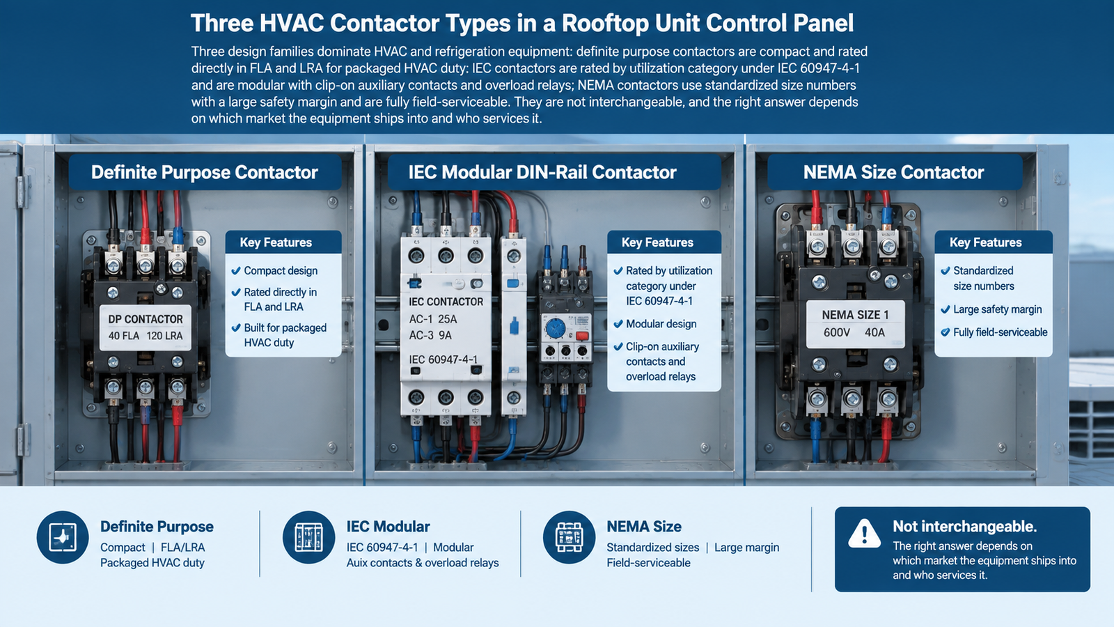
Three design families dominate HVAC and refrigeration equipment. They are not interchangeable, and the right answer depends on which market the equipment ships into and who services it.
Definite purpose contactors were developed specifically because HVAC loads are lighter duty than general industrial motor loads, and paying for a heavy-duty general purpose contactor was a mismatch. DP contactors are compact, inexpensive, and rated directly in HVAC terms: FLA and LRA, plus resistive amp ratings for electric heat. They are the default on residential condensers, unitary equipment, and many commercial rooftop units.
Two procurement details matter. First, many DP contactors carry UL Recognized Component status rather than a UL Listing as a standalone device — verify the specific part number’s file status if the contactor goes into a field-assembled panel or a listed assembly. Second, DP contactors are largely non-serviceable: when the contacts or coil fail, the whole device is replaced rather than repaired. That is a design choice, not a defect, and it keeps field replacement fast.
IEC contactors are rated by utilization category under IEC 60947-4-1, which makes them precise rather than conservative. A given frame carries a different current rating for AC-1, AC-3, and AC-4 duty, so the same physical size can legitimately serve a wide range of loads once you match the category. They are modular: auxiliary contact blocks, surge suppressors, mechanical interlocks, and thermal overload relays clip onto the same frame, and DIN-rail mounting keeps panel space small.
For HVAC equipment built for global markets — and for panels where space is tight — IEC contactors are usually the better fit. For hermetic compressors and fan motors, the governing rating is AC-3.
NEMA contactors use standardized size numbers and carry a deliberately large safety margin. They are physically bigger and more expensive per amp, but they are fully serviceable: coils and contacts can be replaced in the field. They are the right choice for large chiller starters, cooling tower and pump motors, and any installation where downtime cost dominates purchase price.
| 特徴 | Definite purpose | IEC | NEMA |
|---|---|---|---|
| Primary HVAC fit | Unitary AC, RTUs, refrigeration, electric heat | OEM equipment, global-market panels, space-constrained cabinets | Large chillers, pumps, cooling towers, critical plant |
| Rating basis | FLA / LRA / resistive amps | IEC 60947-4-1 utilization categories | NEMA size, horsepower ratings |
| Footprint | Compact, fixed | Smallest per amp, DIN rail or panel | Large, panel mount |
| Accessories | Minimal | Highly modular — aux contacts, overloads, suppressors | Available, larger format |
| Serviceability | Replace the whole device | Accessories replaceable, main frame usually replaced | Coils and contacts replaceable in place |
| Coil options | Usually 24 V AC, some 120/240 V AC | Wide AC and DC range | Wide AC and DC range |
| Cost position | Lowest | Moderate | Highest |
A practical way to choose: if the equipment is a packaged air-conditioning or refrigeration product with a fixed duty, a DP contactor is normally correct and cheapest. If you are building panels that ship to multiple regions, or you need auxiliary contacts and overload protection on the same frame, use IEC. If the load is a large plant motor where a failure means lost production, use NEMA. Modular IEC frames such as the CJX2-D / LC1-D series cover the mid-range HVAC and OEM duties where a compact, accessory-ready device is needed.
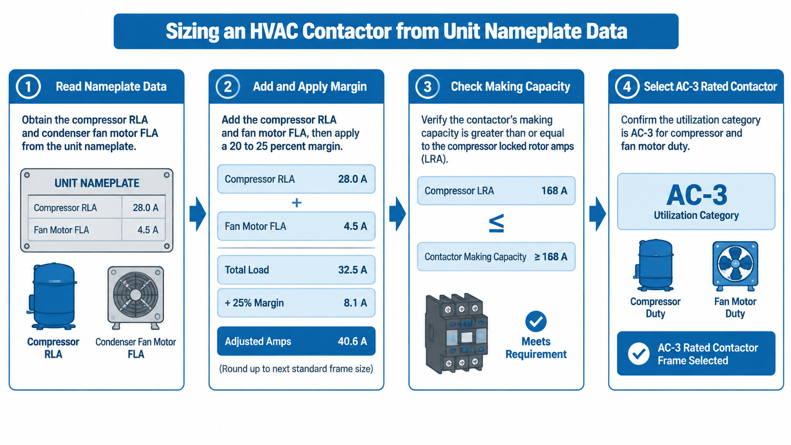
Sizing from the unit nameplate takes four steps and about five minutes. It is more reliable than copying the rating from the failed part, because it catches undersized replacements that were themselves the cause of the failure.
Find the compressor’s Rated Load Amps (RLA) and the condenser fan motor’s Full Load Amps (FLA). On most equipment both appear on the same data plate; on larger units the fan motor data may be on the motor itself. Do not size from tonnage or from nominal horsepower — two units of the same tonnage can differ by 30 % in current draw depending on efficiency, refrigerant, and voltage.
Add compressor RLA and fan FLA, then apply a margin of 20–25 % so the contactor runs cool rather than at its limit. Round up to the next standard frame size. Running a contactor at 100 % of rating inside a hot condenser cabinet shortens contact life for no saving worth having.
This is the step most often skipped. The contactor must survive the compressor’s locked-rotor inrush on every start without welding its contacts. An AC-3 rated device is designed for exactly that making duty. If the contactor is rated only for resistive current — an AC-1 or a heater-only rating — it may carry the running amps comfortably and still weld shut within a season.
Compressors and fan motors are AC-3 loads. Resistive electric heat is AC-1. If a unit cycles its compressor frequently — short-cycling from an undersized system, a bad thermostat, or a control fault — the contactor’s electrical life falls proportionally, and a heavier frame or a higher-cycle device is justified even though the amps have not changed.
| Worked example: 5-ton rooftop unit, three-phase 460 V | Value | Source |
|---|---|---|
| Compressor RLA | 18.0 A | Unit nameplate |
| Condenser fan FLA | 2.0 A | Unit nameplate |
| Subtotal | 20.0 A | 18.0 + 2.0 |
| With 25 % margin | 25.0 A | 20.0 × 1.25 |
| Next standard frame | 32 A AC-3 | Rounded up, IEC AC-3 rating |
| Making capacity check | Must exceed compressor LRA | Nameplate LRA, typically 5–6× RLA |
| Poles | 3-pole | Three-phase compressor and fan |
| Coil | 24 V AC | Unit control transformer |
For a general-purpose motor duty walkthrough — including the motor power to AC-3 frame mapping — see the contactor sizing and selection chart. For contactor-and-overload combinations on motor starters, the motor starter selection guide covers the protection side.
Pole count follows the circuit the contactor switches, not the tonnage. Getting it wrong is either a safety problem or an unnecessary cost.
| System | Poles | 理由 |
|---|---|---|
| Single-phase 208–240 V split or condensing unit | 2-pole | Breaks both legs for a complete disconnect to the compressor |
| Single-phase unit with crankcase heater on a separate circuit | 2-pole + auxiliary contact | Keeps the heater circuit independent of the compressor switching |
| Three-phase 208 / 230 / 460 / 575 V RTU or packaged unit | 3-pole | Switches all three lines simultaneously |
| Three-phase with neutral, or staged electric heat | 4-pole | Switches the neutral or an additional heating stage on the same coil |
| Two-speed or part-wind compressor | Two interlocked contactors | Mechanical interlock prevents both from closing together |
| Wye-delta (star-delta) chiller starter | Three contactors with timer | Main, delta, and star contactors sequence the start |
Using a 3-pole contactor on a single-phase circuit is common in practice because the third pole is simply left unused, but it wastes panel space and adds cost on volume orders. If a specification calls for a 3-pole device on single-phase equipment, confirm whether the extra pole is reserved for a future heating stage before accepting it.
HVAC contactors rarely operate at the ambient temperature printed on the datasheet. A condenser cabinet in direct sun, a rooftop penthouse, or a mechanical room beside a boiler can hold the contactor at 55–70 °C while the outdoor air reads 35 °C. IEC contactors are normally rated at 40 °C ambient, and current capacity falls above that.
| Cabinet ambient | Practical effect | Specification response |
|---|---|---|
| Up to 40 °C | Rated current applies as published | Standard frame selection |
| 40–55 °C | Noticeable loss of continuous current capacity | Step up one frame size, or apply the manufacturer’s derating curve |
| 55–70 °C | Coil insulation and contact springs age faster; capacity loss is significant | Larger frame plus a higher coil insulation class |
Three related factors deserve the same attention:
Lower-GWP A2L refrigerants such as R-32 and R-454B do not change the contactor’s electrical duty, but they do tighten the component-approval requirements on the equipment as a whole. Confirm that the contactor and its surrounding components are approved for the refrigerant and equipment standard the unit is certified to.
Replacement is where most avoidable callbacks happen. The rule is simple: the new contactor must match or exceed the original on every electrical rating, and match exactly on coil voltage and mounting footprint. Recording the following before removal takes two minutes and prevents a second site visit.
| Field to record | Where to find it | Rule |
|---|---|---|
| Coil voltage | Old contactor label, or control circuit measurement | Exact match required |
| Coil frequency | Label (50 Hz / 60 Hz / dual) | Must match the supply |
| Continuous current rating | Old label, confirmed against unit nameplate RLA + FLA | Equal or higher |
| Making / LRA rating | Old label, confirmed against nameplate LRA | Equal or higher |
| Pole count | Old contactor and circuit configuration | Exact match |
| Load category | Old label (AC-3, or DP FLA/LRA ratings) | Equal or better duty |
| Terminal type and wire size | Old contactor terminals | Must accept existing conductors |
| Mounting footprint and height | Old contactor and enclosure | Must fit without modification |
| Auxiliary contacts | Old contactor, wiring diagram | Count and NO/NC state must match |
| Ambient and enclosure rating | Equipment location | Match or exceed the original |
Two rules override convenience. Never fit a contactor with a lower current or making rating than the original, even temporarily — the compressor’s inrush will find the weak point. And never substitute a different coil voltage because the control transformer “probably” has a tap for it; the coil is the one rating that cannot be traded off against anything else. Budget expectations for parts, labor, and downtime are covered in the AC contactor replacement cost breakdown.
Before ordering, confirm the failure is actually the contactor. Welded contacts, an open coil, and a burned terminal all present as “the unit will not start,” but so does a failed thermostat, a blown control fuse, and a tripped overload. The signs of a failing AC contactor guide walks through the electrical checks that separate a contactor fault from a control fault.
Contactors in air-conditioning equipment are consumables. Their life is governed by the number of starts, the inrush they absorb, and the temperature they sit in — not by calendar age. Three habits extend it:
HVAC contactor selection comes down to matching four things to the equipment: coil voltage, continuous current, making capacity, and pole count — with the utilization category and cabinet ambient deciding how much margin you actually need. Definite purpose contactors win on packaged HVAC and refrigeration products, IEC contactors win on global OEM equipment and space-constrained panels, and NEMA contactors win where a failure is expensive.
If you are specifying contactors for a new equipment line or replacing units across a fleet, compare the compact LC1-D series contactors against the CJX2-D range on footprint, coil options, and auxiliary-contact availability, or send the nameplate data to our engineering team and we will match the frame to the duty.
A contactor is built to switch higher currents and is designed to be replaced rather than repaired; a control relay handles low-current control circuits and usually carries multiple poles with lower ratings. In HVAC equipment both are present — the thermostat signal may pass through a relay or a control board before energizing the contactor coil.
Most packaged air-conditioning and heat pump equipment uses a 24 V AC coil driven by the unit’s control transformer. Commercial and older equipment may use 120 V AC or 208–240 V AC coils. The coil voltage must match the control circuit exactly; a mismatch means the contactor either will not pull in or will burn out.
Yes, provided the coil voltage, pole count, terminal type, and mounting footprint match. A higher current and making rating gives more thermal headroom and generally lasts longer. A lower rating is never acceptable, because the compressor’s locked-rotor inrush can weld the contacts.
Single-phase 208–240 V equipment normally uses a 2-pole contactor so both legs are broken. Three-phase equipment uses a 3-pole contactor. Four-pole devices are used where the neutral is switched or where an additional electric heat stage is controlled by the same coil.
The common indicators are a unit that will not start, audible chattering, a burnt smell, or a compressor that runs continuously and will not shut off. Welded contacts cause continuous running; an open coil causes no pull-in at all. Confirming which one has failed requires voltage and resistance measurements at the coil and contacts.
No contactor is truly universal. A general purpose IEC contactor can be substituted for a definite purpose contactor if its AC-3 rating, coil voltage, pole count, and footprint match the application, and if its UL status suits the assembly it goes into. Matching the electrical ratings exactly matters more than matching the product family name.