AC-15 vs DC-13: Auxiliary Contact Ratings Explained
AC-15 gives a contact 4 A at 240 V; DC-13 gives the same contact 0.3 A at 250 V. The categories, the test duties behind them, and the PLC dry-circuit floor.
Read More
Two contactors can carry the same 115 A, close in the same 20 milliseconds and cost almost the same to buy — yet one of them burns 300 kWh a year just staying closed, and the other burns almost nothing. The difference is the holding mechanism. Permanent magnet (PM) contactors hold closed with a magnet; electromagnetic (EM) contactors hold closed with a coil that never stops drawing power. This page puts numbers on that holding loss, then compares voltage-dip behavior, failure modes and total cost so you can decide where the PM premium actually pays back.
| Property | Electromagnetic (EM) | Permanent magnet (PM) |
|---|---|---|
| Holding force source | Energized coil, continuously | NdFeB magnet in the armature circuit |
| Holding power draw | 8–35 VA depending on frame | ~0 W; electronics module 0.5–2 W |
| Coil behavior on close | Inrush 5–10× sealed current, then sealed | Short pulse (~0.1–0.3 s), then off |
| Open command | Remove coil power; spring opens | Reverse-polarity pulse; spring assists |
| Voltage dip ride-through | Drops out below ~20–75 % Uc | Unaffected — no holding coil to starve |
| Loss of control power | Contactors open (fail-safe) | Stays closed (must be designed for) |
| Purchase price | Baseline | Roughly 1.5–2.5× for the same frame |
Note the last two rows together: PM contactors are immune to dips and they do not open when control power fails. Depending on your process, that is either the main selling point or the main objection.
In an EM contactor the closed state is a tug-of-war: the coil’s magnetic force pulls the armature against the opening spring. Every hour, every year, the coil stays energized. The coil is sized so its sealed current produces enough force with margin — which is why IEC 60947-4-1 requires reliable pickup between 85 % and 110 % of rated control voltage, and why a starving coil turns into the buzzing and chatter problems described in our contactor buzzing diagnosis guide.
A PM contactor borrows its closed-state force from a permanent magnet built into the magnetic circuit. The coil works only during the transition: one polarity pulse closes, the opposite polarity opens. Between commands the coil is electrically idle. Mechanically it is close to a latched design — the latching, reversing and vacuum contactor families cover the mechanical-latch variant, which achieves the same “coil off while closed” result with a latch instead of a magnet.
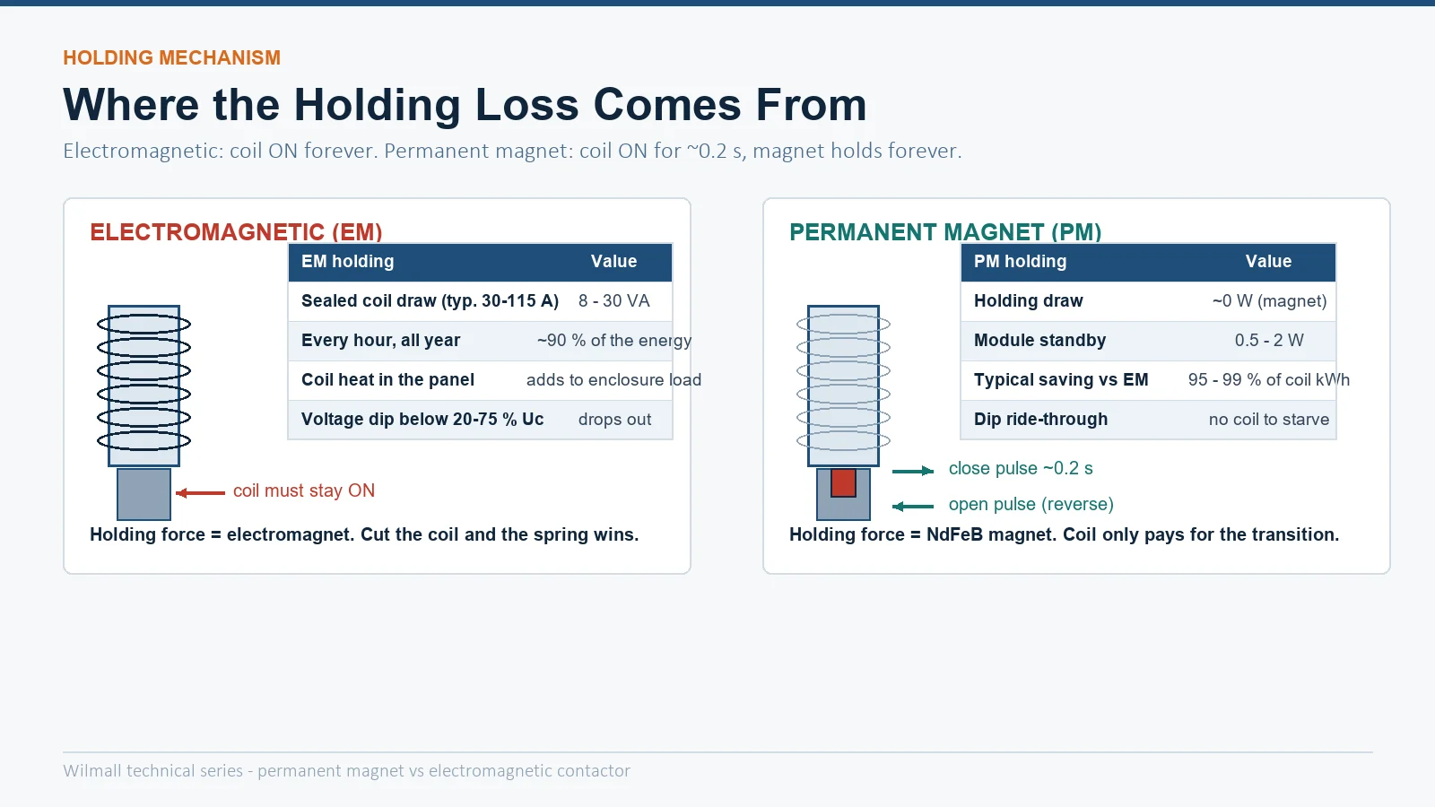
Sealed coil consumption for typical 3-pole AC contactor frames ranges from about 7 VA on a 9 A frame to 35 VA and up on a 630 A frame. Held closed for a full year (8 760 h), those watts are pure standing loss — heat in the panel and money on the meter:
| Frame | Sealed coil (typ.) | EM kWh/year | PM kWh/year | Saving per unit/year at $0.12/kWh |
|---|---|---|---|---|
| 9–12 A | 7 VA | ≈ 61 kWh | ≈ 0.4 kWh | ≈ $7 |
| 25–32 A | 12 VA | ≈ 105 kWh | ≈ 0.7 kWh | ≈ $12 |
| 80–115 A | 20 VA | ≈ 175 kWh | ≈ 1.0 kWh | ≈ $21 |
| 400–630 A | 35 VA | ≈ 307 kWh | ≈ 1.5 kWh | ≈ $37 |
The fleet effect is where this stops being trivia. A motor control panel with 40 contactors averaging 15 VA of holding draw wastes roughly 525 kWh per year as coil heat — and that heat has to be ventilated out of the enclosure, driving enclosure sizing and fan/air-conditioning load. Published engineering studies and vendor measurements put real-world savings at 95–99 % of holding energy; one cited 220 V comparison measured 17.4 VA (EM) versus 3.0 VA (PM with its electronics running), and large-frame Chinese CJ20-style PM retrofit claims reach four-digit kWh savings per contactor per year.
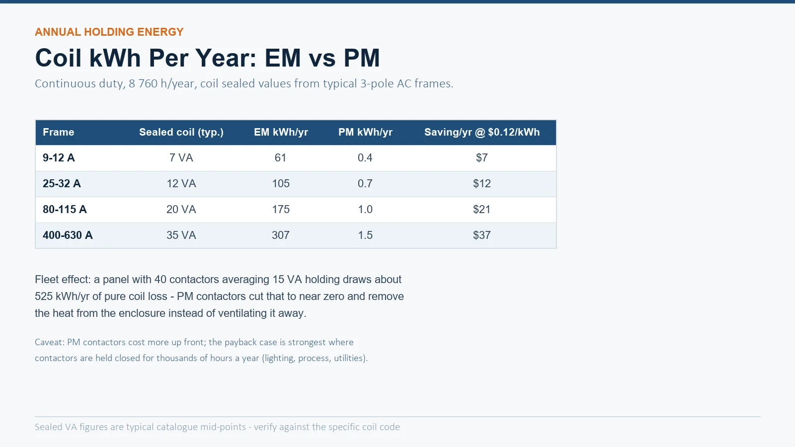
The second loss is not measured in kWh but in stoppages. An EM contactor must release between roughly 20 % and 75 % of Uc — that is the IEC window — so a grid dip that lasts a few cycles drops out every contactor in the plant at once. Continuous-process plants call this 晃电 (voltage sag) and it is expensive: a single sag event can idle a production line for hours of restart.
A PM contactor has no holding coil to starve. Its state is magnetic, not electrical, so sags ride through unnoticed — unless you deliberately program the electronics module to release on a defined dip threshold or after a timed delay. That programmability is worth stating precisely: PM contactors give you a choice between ride-through and immediate release, where EM contactors only do one thing.
| Failure mode | EM contactor | PM contactor |
|---|---|---|
| Coil burnout | Common — inrush heating, over/under-voltage, partial shorted turns | Rare — coil is de-energized most of its life; electronics module is the new weak point |
| Fails to release | Welded contacts, sticky armature (see our stuck-closed diagnostic) | Welded contacts, plus remanence/demagnetization issues unique to the magnet |
| Overheating from coil | Contributes to enclosure heat load permanently | Negligible |
| High ambient | Coil insulation ages continuously while energized | Magnet grade sets a max operating temperature (typically 80–150 °C for NdFeB grades) — check the datasheet for hot-panel service |
| Control wiring fault | Wire falls off → contactor opens (visible) | Module fault may leave state frozen — needs feedback contacts to verify |
Payback is strong when: contactors stay closed for thousands of hours a year (lighting feeds, process utilities, building services, remote or solar-powered sites), panel heat is a design constraint, or voltage sags are costing real downtime. In those cases the energy saving plus sag immunity can return the price premium within a few years, and the cooler panel is a permanent dividend.
Stick with EM when: the load cycles frequently (holding loss barely accumulates and the duty-cycle limits in our duty cycle and operating frequency guide dominate instead), when the safety concept depends on contactors dropping out on loss of control power (see the force-guided safety contactor discussion), or when the maintenance team has no experience diagnosing magnet-driven mechanisms. The utilization-category sizing itself is unchanged — an AC-3 motor load is selected the same way for both, per our AC-1 to AC-4 category guide.
For most industrial motor feeders in the 9–630 A range, a standard electromagnetic contactor such as our CJX2-F series (115–800 A) remains the economic default — browse the full AC contactor range for frame options and coil codes.
An EM contactor is wired the way every maintenance electrician expects: a maintained or momentary signal into A1–A2, seal-in contact across the start button, drop-out on loss of signal. A PM contactor’s coil is a pulse-driven device, and the control scheme must reflect it:
None of this is difficult, but it is different — and “different” is the real cost driver for retrofit projects, alongside the purchase premium. Budget engineering time for the first installation even when the hardware is plug-compatible.
Essentially. The magnet provides the holding force; only the electronics module (0.5–2 W) stays alive to watch for commands. Compared with 8–35 VA of continuous coil draw, that is a 95–99 % reduction in holding energy.
They solve the same problem differently. A latching (mechanically held) contactor uses a mechanical latch; a PM contactor uses magnet force. Both hold closed with the coil off — see our types comparison for the trade-offs of each mechanism.
Usually yes at the same frame size, but verify three things: the control scheme must send a polarity-reversed pulse (or a paired close/open output) instead of a maintained signal, any “contactor proved open” interlocks must be revalidated, and the safety case must accept that control-power loss no longer opens the contactor.