Motor Thermal Damage Curve vs Relay Trip Curve
Six points, two lines, three conditions. Plot the thermal damage curve against the relay trip curve and know exactly what the overlaps mean.
Read More
Thermal overload relays have protected motors for a century by modelling heat with a bimetallic strip, and they still do it adequately on a direct-on-line starter in a temperate panel. Put the same relay downstream of a variable frequency drive, or on a high-inertia load that takes forty seconds to accelerate, and the model stops matching reality: the relay trips on waveform content it was never designed for, or fails to trip because the motor’s cooling has changed while the relay’s assumption has not.
This guide compares thermal (bimetal) and electronic overload relays on the three factors that decide the choice in practice — trip accuracy, inverter duty, and high-inertia starting — and then sets out where each one belongs. It assumes the motor protection basics are already understood; for the bimetal mechanism itself see how a thermal overload relay works, and for setting trip classes see NEMA class 20 versus IEC class 10.
| Property | Thermal (bimetal) | Electronic |
|---|---|---|
| Sensing principle | Bimetal strip heated by current through a heater element | Current transformers (or shunts) feeding a measurement circuit |
| Trip accuracy | Wide scatter; influenced by ambient and mounting | Tight, repeatable, largely ambient-independent |
| Ambient compensation | Available on compensated versions only | Inherent |
| Trip class | Fixed per heater/relay (10, 20, 30) | Selectable in the field, often 5/10/20/30 |
| Phase loss / imbalance | Detected only via the differential bar, approximately | Measured directly, with separate thresholds |
| Waveform response | Frequency- and harmonic-sensitive — a real limit on drive output | True-RMS measurement, designed for distorted waveforms |
| Thermal memory | Physical, but cools during a power interruption | Can model cooling and retain state across a supply dip |
| Diagnostics | Trip / no trip | Current values, imbalance, thermal capacity used, alarm before trip |
| コスト | Baseline | Roughly 2–4× the thermal equivalent |
The short version: thermal relays model heat physically; electronic relays measure current and calculate heat. The physical model is cheap and robust but it inherits the limitations of the physics — ambient, frequency, waveform. The calculated model is accurate and flexible but needs a measurement circuit, and often an auxiliary supply.
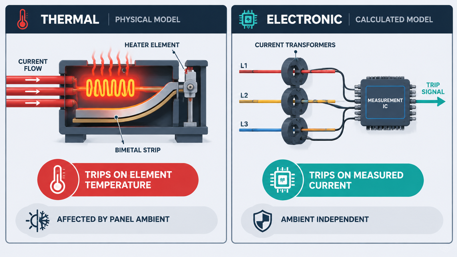
A bimetal relay trips when its strip reaches a temperature, and that temperature comes from two sources: the current through the heater, and the surrounding air. That is the root of every limitation that follows.
None of these is a defect. They are the consequences of modelling thermal behaviour with a heated strip, and on a direct-on-line application running near rated speed in a normal panel, they all fall inside the tolerance that IEC 60947-4-1 allows.
It is worth knowing what the trip requirement really is, because it explains why “accuracy” matters less than most buyers assume on DOL duty — and more than they assume on everything else.
| Condition (IEC 60947-4-1, three-pole, from cold) | Required behaviour |
|---|---|
| 1.05 × set current | Must not trip within 2 hours |
| 1.20 × set current | Must trip within 2 hours |
| 1.50 × set current | Trip within the time given by the trip class |
| 7.2 × set current | Trip within the time given by the trip class |
That 1.05-to-1.20 window is the legally permitted scatter band. A thermal relay sitting anywhere inside it is compliant, which means two units from the same batch can trip at meaningfully different currents and both be correct. On a motor with generous thermal margin, that scatter is harmless. On a motor running close to its thermal limit, or on a motor whose cooling is compromised, it is the difference between nuisance trips and a burned winding.
An electronic relay tightens that window considerably by measuring current directly. It also lets you separate the trip threshold from the alarm threshold, which is the more useful capability in practice: an alarm at 95% of thermal capacity lets you intervene before the trip, and no bimetal relay can do that.
Variable frequency drives change the question in three distinct ways, and the placement of the relay matters as much as its type.
Downstream of a drive, the motor current is a PWM waveform with a high harmonic content and a carrier frequency in the kilohertz range. A bimetal heater sees this as significantly more heating than the fundamental current implies, and the error grows with carrier frequency and cable length. Most manufacturers either prohibit this arrangement or require specially rated heaters. The practical alternatives are:
On the supply side, the current is near-sinusoidal but carries the rectifier’s harmonic spectrum. A thermal relay here is less badly affected than on the output, but it still measures heating rather than fundamental current, which matters on a drive with a high total harmonic distortion. On the input side the relay is usually protecting the drive, not the motor — so the more relevant protection is the drive’s own input protection rather than a motor thermal model.
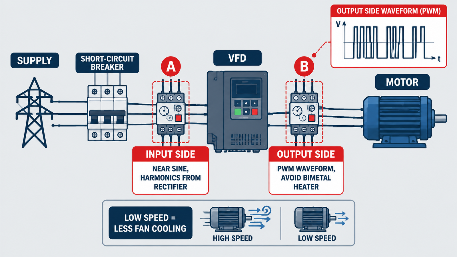
At reduced speed, a shaft-mounted motor fan delivers far less cooling. The motor can overheat at currents well below its nameplate rating. Neither a bimetal relay nor a basic electronic relay knows the speed, so both are blind to this — the standard remedies are to oversize the motor, fit a separately powered fan, or use a relay that accepts a thermistor or a speed signal. That last option is only available on electronic devices, which is one of the strongest arguments for them on inverter-driven loads.
A high-inertia load — a large fan, a centrifuge, a loaded conveyor, a ball mill — takes far longer to accelerate than a normal pump. A class 10 relay will trip during a legitimate start. The conventional fixes are class 20 or 30, or a larger relay, both of which are available in thermal form.
Electronic relays do the same job more precisely: the class is selected by DIP switch or parameter, the trip curve is repeatable, and the device can distinguish a genuine long start from a locked rotor using current level rather than elapsed time alone. The practical difference on a start that lasts 30 to 60 seconds is a relay that trips at the intended point every time, rather than one whose trip time drifts with panel temperature.
Where the load is high-inertia そして inverter-driven — a common combination on large fans — the electronic relay plus the drive’s own model is effectively the only arrangement that protects the motor through both the acceleration and the low-speed running phase.
| 申し込み | Recommended | 理由 |
|---|---|---|
| DOL pump or fan, normal panel, standard start | Thermal, class 10 | Cheapest compliant solution; scatter irrelevant to a motor with thermal margin |
| DOL with long start time | Thermal class 20/30, or electronic | Both work; electronic gives repeatability |
| Motor on VFD output | Drive’s internal model, or electronic inverter-rated relay | Bimetal heaters misread PWM waveforms |
| High-inertia fan or centrifuge with VFD | Electronic plus thermistor or speed input | Cooling loss at low speed must be accounted for |
| Critical motor with remote monitoring | Electronic with communications | Current, thermal capacity and alarms available before trip |
| Panel at high ambient (>45 °C) | Electronic, or compensated thermal | Ambient compensation is inherent, not a curve fit |
| Remote or unmanned site | Electronic with remote reset | Avoids a site visit to reset a trip |
| Legacy replacement, exact form factor | Thermal, like-for-like | No auxiliary supply, drops onto the existing contactor |
Where the relay is being chosen as part of a starter rather than as a standalone device, the overall arrangement — contactor, relay and short-circuit protection — is covered in contactor selection for motor starters, and the alternative of a single manual motor starter combining both functions in overload relay versus MPCB.
| Mistake | Consequence | Correction |
|---|---|---|
| Fitting a standard thermal relay on a drive output | False trips, or heater failure, from harmonic heating | Use the drive’s model or an inverter-rated electronic relay |
| Setting the relay to the motor’s nameplate current in a hot panel | Nuisance trips all summer | Use a compensated or electronic device, or adjust for ambient |
| Assuming thermal relay scatter is negligible | Protection either misses a real overload or trips early | Understand the 1.05–1.20 band; specify tighter where margin is thin |
| Ignoring cooling loss at low speed on a VFD | Winding burnout well below rated current | Oversize, add forced ventilation, or use a thermistor input |
| Using automatic reset on a genuinely overloaded motor | Repeated restarts into a hot winding | Manual or remote reset, with the cause investigated |
| Expecting the relay to clear a short circuit | Device destruction; no fault current rating | Rely on the upstream breaker or fuse, with Type 1/2 coordination |
Yes, in two senses: it measures current directly rather than inferring it from heater temperature, and it is largely immune to panel ambient. Thermal relays are permitted a scatter band between 1.05 and 1.20 times the set current under IEC 60947-4-1; electronic devices hold a much tighter window.
Not on the drive output with standard heaters. PWM output contains harmonic content that overheats the bimetal heater and causes false trips. Use the drive’s internal electronic protection, or a relay explicitly rated for inverter duty.
Some are self-powered from the load current and need no auxiliary supply; others require 24 V DC for the measurement and communication circuits. Check this before ordering, because it determines whether the device is a drop-in replacement.
Class 20 or 30 for a start that takes longer than a normal DOL acceleration, with the exact class set from the manufacturer’s starting-time data. Electronic relays allow the class to be selected in the field, which makes adjustment after commissioning practical.
Because a non-compensated thermal relay responds to ambient temperature as well as current. Above roughly 40–45 °C the effect becomes significant. Options are a compensated thermal relay, an electronic relay, or derating the setting — the last is least satisfactory because it reduces protection.
Usually yes. Most electronic overload relays measure all three phases and provide phase-loss, phase-imbalance and often ground-fault protection, which removes the need for separate phase-failure devices and simplifies the panel.
Thermal relays are not obsolete; they are simply a physical model with physical limits, and those limits fall outside the application on inverter duty, high ambient, long starts and anything where you want an alarm before a trip. Choose thermal for straightforward DOL duty where the motor has thermal margin and the panel is normal. Choose electronic where the waveform is distorted, the cooling assumption is wrong, the ambient is high, or the trip needs to be visible before it happens — and remember that on a VFD output the drive’s own thermal model is often the correct primary protection. For thermal relays covering the standard DOL range, including the CR2 series from 0.1 A to 630 A, see the CR2 thermal overload relay page, and the AC contactor category for the matching contactors.