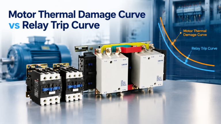
Motor Thermal Damage Curve vs Relay Trip Curve
Six points, two lines, three conditions. Plot the thermal damage curve against the relay trip curve and know exactly what the overlaps mean.
Read More
MPCB selection is usually described as one decision — “pick the breaker that covers the motor current” — and that is why so many panels end up with a device that trips on every start or cannot clear a fault. A motor protection circuit breaker makes three separate decisions: the thermal dial, the frame (which fixes the magnetic trip and the breaking capacity), and the coordination with the contactor that does the actual switching.
This guide separates those decisions, gives the numbers to check against, and works through a selection where the obvious answer is wrong. It assumes you have already decided an MPCB is the right device for the job; if that is still open, the comparison against a breaker-plus-relay starter is covered in thermal overload relay vs MPCB.
Two independent decisions, in this order:
The dial protects the winding from sustained overload. The frame protects the circuit from fault current and decides whether the motor can start at all. Choosing a bigger frame to get a wider dial range moves the magnetic threshold up with it, and choosing a smaller frame to save panel space can leave the installation with insufficient breaking capacity. The two are linked through the frame, which is why the dial alone is never the whole selection.
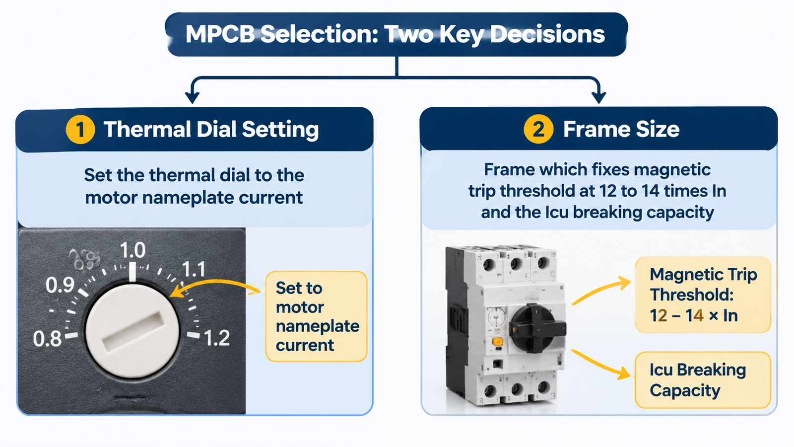
Start from the nameplate current at the voltage the motor will actually run at, not the catalogue current for a nominal voltage. A motor nameplated 400 V and installed on a 380 V system draws more current at the same shaft load; a motor reconnected from star to delta changes the current the relay sees by a factor of √3.
Then place the setting inside the adjustable range rather than at its edge. A 22 A motor on a 20–25 A device has almost no upward flexibility; on an 18–25 A device it sits comfortably, which matters when the driven load turns out heavier than the datasheet suggested. Oversizing the range to “leave room” is the opposite mistake: a 22 A motor on a 50–63 A device cannot be set accurately at all, because the dial’s resolution at that end is coarse and the protection band becomes wide.
Service factor is the only legitimate reason to set above nameplate current, and only where the driven load genuinely uses the margin. For the setting arithmetic in more depth, including star-delta delta-leg mounting, see overload relay field setting.
The frame fixes the magnetic trip threshold and the breaking capacity together. That is the point most often missed when a device is chosen purely on current range.
Motor-protection frames typically place the fixed magnetic threshold at about 12–14 × In, deliberately high so a direct-on-line start is not read as a fault. A standard motor pulls 6–8 × FLC during run-up, and high-efficiency or high-inrush designs can go higher. A threshold set too low produces a trip in the first few cycles of every start; a threshold set too high lets a genuine short circuit persist long enough to damage the contactor before the device operates.
This is exactly where a general-purpose miniature breaker fails the application. A Type C device trips magnetically at 5–10 × In, so a 10 A motor drawing 60 A of locked-rotor current opens the breaker instantly. A Type D at 10–20 × In may survive the start but is a blunt instrument with no adjustable thermal element. The comparison is worth keeping in view:
| Device | Magnetic threshold | Thermal adjustment | Typical Icu at 400 V | Fits motor starting? |
|---|---|---|---|---|
| Type C MCB | 5–10 × In, fixed | None | 6–15 kA | No — trips on inrush |
| Type D MCB | 10–20 × In, fixed | None | 6–15 kA | Marginally — no overload protection |
| MPCB, small frame | ≈12–13 × In, fixed | Adjustable dial | 50–100 kA with correct backup | Yes, for DOL and star-delta |
| MPCB, magnetic-only | Fixed, frame-defined | None — needs separate relay | Frame-dependent | Yes, where jam or underload detection is needed |
Icu must exceed the prospective short-circuit current at the point of installation, and that number comes from the supply, not from habit. A remote pump panel fed by a long cable run usually has a lower fault level than a main switchboard because cable impedance limits it — but “remote” is not a guarantee. A short run from a nearby transformer can still deliver a fault current that the smallest frame cannot clear.
Two ratings matter and are often quoted interchangeably: Icu is the ultimate breaking capacity the device survives once, and Ics is the service breaking capacity it survives repeatedly. For a device that may see more than one fault in its life, Ics is the number that decides whether it is still a breaker afterwards.
A 400 V, 18.5 kW conveyor motor, nameplate FLC 35 A, direct-on-line start with a measured 8 second run-up, fed from a panel with a calculated prospective fault current of 22 kA.
Now the trap. If someone selects a 40–63 A frame “so there is headroom”, the magnetic threshold moves to roughly 480–820 A and the thermal dial can no longer be set accurately at 35 A. The motor loses overload protection at the low end and the panel gains nothing at the high end. Frame choice is not a safety margin you can spend.
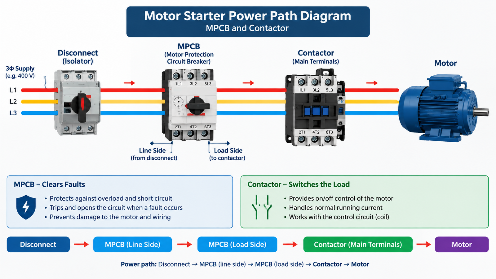
An MPCB provides overload protection, short-circuit protection and manual isolation. It does not provide frequent remote switching, PLC-controlled operation or automatic reversing. Those are the contactor’s job, and the two devices are a pair rather than substitutes.
Practically, the power path runs from the disconnect to the MPCB line side, from the MPCB load side to the contactor’s main terminals, and from the contactor to the motor. The MPCB clears faults; the contactor switches the load thousands of times a year. Sizing the contactor is a separate exercise in AC-3 duty, covered in how to size and select a contactor.
For a matched set, the CJX2-F series contactors cover the frame sizes that sit behind MPCBs in this current band, and the CJX2 series covers the smaller DOL starters where a compact breaker-plus-contactor assembly is the whole starter.
Some loads need protection a bimetal cannot provide: a pump running dry draws less current than a loaded one, so no overcurrent element will ever see it; a jammed conveyor may sit just above normal current for a long time before the thermal element reacts. In those cases a magnetic-only MPCB paired with an electronic overload relay that offers underload or jam detection is the better architecture.
The trade-off is wiring and panel space: two devices, more terminations, and a coordination question that the manufacturer’s tables no longer answer for you. Where the load is a standard fan, pump or conveyor with predictable behaviour, the thermal-magnetic frame remains the simpler and cheaper choice.
| Check | Target | Common failure |
|---|---|---|
| Nameplate current at actual voltage | Dial range covers it, setting near mid-range | Using catalogue current at nominal voltage |
| Starting method and inrush multiple | Inrush below the frame’s magnetic threshold | Frame chosen on current only |
| Prospective fault current | Icu above it, with the specified backup device | Assuming a remote panel has a low fault level |
| Service breaking capacity | Ics adequate for repeat faults | Quoting Icu as if it were Ics |
| Coordination type | Type 2 with the specified contactor, per tested tables | Pairing frames that were never tested together |
| Isolation and lockout | Device marked suitable for isolation, or a separate disconnect | Treating the breaker handle as the only lockout point |
One further check that belongs on the list for export projects: whether the assembly needs UL 508 recognition for the destination market. An IEC-only MPCB may be perfectly compliant at home and unusable in a North American panel. That split is discussed in NEMA Class 20 vs IEC Class 10, which covers the same standards divergence for the overload element.
Select the dial for the motor and the frame for the fault, and keep the two decisions separate in your head. Confirm the nameplate current at the real voltage, check that the frame’s fixed magnetic threshold clears the actual inrush, verify Icu and Ics against a calculated fault level, and confirm the contactor pairing is a tested combination. The device that results is unremarkable in the best way: it starts the motor every time and clears a fault without anyone having to explain it afterwards.
An MCB has fixed trip characteristics and protects cables and general circuits. An MPCB has an adjustable thermal element set to the motor current and a magnetic threshold placed high enough to ride through motor inrush, plus a breaking capacity suited to motor branch circuits.
No. It can switch manually through its handle, but it is not built for frequent remote operation, PLC control or reversing duty. Standard starters use an MPCB for protection and a contactor for switching.
Use an MPCB where panel space and wiring simplicity matter and the load is a standard motor. Use a breaker plus relay where the overload protection needs to be remote, adjustable in class, or capable of underload and jam detection.
The magnetic threshold is too close to the motor’s inrush. Check the actual starting current multiple and the frame’s fixed threshold; if they overlap, move to a frame with a higher magnetic setting rather than adjusting the thermal dial, which has no effect on the magnetic element.
Only where the service factor is genuinely used, up to roughly 115% of FLC on an SF 1.15 motor. Setting high to stop nuisance trips removes overload protection and is the usual cause of preventable winding failures.
After a short circuit, the starter remains serviceable with only light contact damage permitted. It is a property of the tested combination of breaker, contactor and backup device, not of the MPCB alone.