


PG9ケーブルグランドドイツのネジサイズと仕様ガイド
The PG9 cable gland represents one of the most widely specified mid-range PG thread sizes in industrial electrical installations across Europe and global markets. As a German thread standard defined under DIN 46320, PG9 cable glands accommodate cable diameters from 4mm to 8mm, making them ideal for control panel wiring, sensor connections, and light industrial equipment applications. Understanding PG9 cable gland German thread specifications ensures proper component selection, installation compliance, and long-term system reliability. This comprehensive reference guide covers dimensional standards, material options, conversion equivalents, and practical application scenarios to help engineers, procurement specialists, and installation technicians specify the correct PG9 cable gland for their specific requirements.
Understanding PG Thread Standards and DIN 46320
PG (Panzergewinde) thread designations originated in Germany as a parallel thread system specifically designed for electrical cable gland applications. Unlike metric threads which use millimeter-based sizing, PG threads employ a numerical designation (PG7, PG9, PG11, etc.) that doesn’t directly correspond to the thread’s outer diameter. The PG9 designation specifically refers to a thread with an outer diameter of 15.2mm and a thread pitch of 1.41mm.
The governing standard for PG cable glands is DIN 46320, which establishes construction requirements, dimensional tolerances, and performance criteria. This standard specifies that PG9 cable glands must provide secure strain relief, environmental sealing, and electrical continuity where required. Compliance with DIN 46320 ensures interchangeability between manufacturers and verifiable performance characteristics for procurement specifications.
Key PG9 Thread Specifications
The technical specifications for PG9 cable gland German thread are:
- Thread designation: PG9
- Outer diameter: 15.2mm
- Thread pitch: 1.41mm (approximately 18 threads per inch)
- Panel cutout diameter: 15.2mm + 0.2mm tolerance
- Thread engagement length: Typically 5-6mm depending on gland design
- Thread angle: 80° flank angle (wider than metric 60° or NPT 60°)
The PG9 thread features parallel (straight) threads on both male and female components, unlike NPT tapered threads. This parallel design allows for easier assembly and disassembly while maintaining seal integrity through compression gaskets rather than thread interference.
PG9 Cable Diameter Range and Sizing
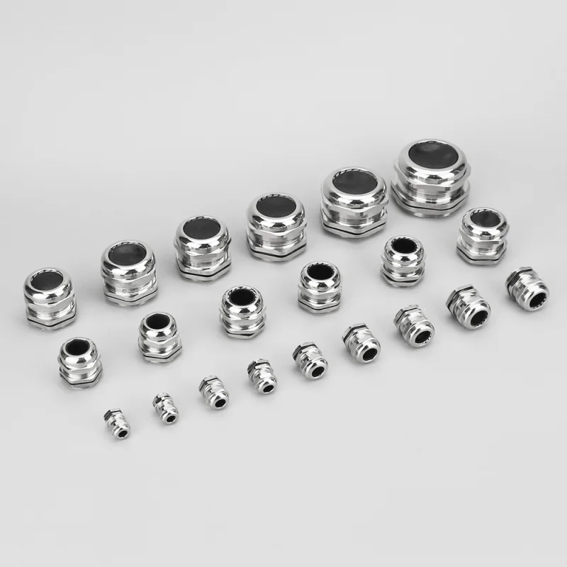
The defining characteristic of PG9 cable glands is their accommodation of cable outer diameters ranging from 4mm to 8mm. This mid-range capacity makes PG9 ideal for:
- Control wiring: Multi-conductor cables for PLC inputs, relay controls, and sensor signals
- Instrumentation cables: Thermocouple wire, RTD sensor cables, and measurement circuits
- Communication cables: Industrial Ethernet, RS-485, and fieldbus networks
- Power distribution: Low-voltage DC power supplies and LED lighting circuits
- Automation sensors: Proximity sensors, photoelectric sensors, and limit switches
Proper cable sizing within the PG9 range ensures adequate compression seal engagement. Cables smaller than 4mm require reducing bushings or alternative gland sizes (PG7), while cables exceeding 8mm necessitate upgrading to PG11 or larger specifications.
Cable Range Verification Process
Before specifying PG9 cable glands, measure the cable outer diameter including any jacket, sheath, or armor layers:
- Use precision calipers to measure cable OD at multiple points
- Account for cable ovalness by taking maximum dimension
- Add 0.5-1mm for manufacturing tolerances and compression allowance
- Verify the resulting dimension falls within 4-8mm range
- Confirm cable construction (unarmoured, braided shield, etc.) matches gland sealing design
Cables with irregular cross-sections, such as flat ribbon cables or multi-core bundles, may require special PG9 gland variants with elongated seal openings.
Material Options for PG9 Cable Glands
PG9 cable glands are manufactured in multiple material configurations to suit different environmental and mechanical requirements.
Nickel-Plated Brass PG9 Glands
Nickel-plated brass represents the standard material for industrial PG9 cable glands. These metal glands offer:
- Excellent mechanical strength for vibration resistance
- Corrosion protection through nickel plating (typically 5-8 microns thick)
- Temperature range from -40°C to +100°C
- Electrical continuity for EMI shielding and grounding
- IP65 or IP68 rating when properly installed with sealing washers
- Flame resistance and outdoor UV stability
Brass PG9 glands comply with DIN 46320-C4-MS specifications and are suitable for industrial control panels, motor junction boxes, and outdoor electrical enclosures.
Nylon/Polyamide PG9 Cable Glands
Nylon 66 (polyamide) PG9 cable glands provide a lightweight, corrosion-proof alternative for non-metallic applications. Characteristics include:
- Chemical resistance to oils, solvents, and cleaning agents
- Non-conductive for isolation requirements
- Temperature range from -20°C to +80°C (standard grades)
- IP54 to IP68 ratings depending on seal design
- Lower cost than metal equivalents
- Available in multiple colors (black, gray, light gray) for coding
Nylon PG9 glands are ideal for plastic enclosures, food processing equipment, and applications where electrical isolation or weight reduction is critical.
Stainless Steel PG9 Glands
For harsh chemical, marine, or high-temperature environments, stainless steel 316 PG9 cable glands offer maximum corrosion resistance. These premium glands withstand:
- Saltwater and marine atmospheres
- Acidic or alkaline chemical exposures
- Temperature extremes up to +200°C (special high-temp seals)
- High-pressure washdown (IP69K variants)
- Hygienic cleanroom requirements
Stainless PG9 glands cost 3-5× more than brass but eliminate corrosion-related failures in demanding applications.
IP Rating and Environmental Sealing
PG9 cable glands achieve environmental protection through multiple sealing elements that compress against the cable jacket.
Standard IP Ratings for PG9 Glands
- IP54: Dust protected, splash water resistant (basic polyamide glands)
- IP65: Dust tight, jet water resistant (brass glands with flat gasket)
- IP66: Dust tight, powerful jet resistant (compressed seal design)
- IP67: Dust tight, temporary immersion resistant (double seal variants)
- IP68: Dust tight, continuous immersion (pressure-rated seals)
- IP69K: High-pressure, high-temperature washdown (food industry)
The IP rating depends on both the gland design and proper installation torque. Under-tightening leaves gaps allowing moisture ingress, while over-tightening can damage plastic glands or deform seals.
Sealing Element Configuration
PG9 cable glands employ multiple sealing strategies:
- Compression sealing ring: NBR rubber or elastomer ring compressed radially against cable jacket
- Multi-hole membrane seal: Pre-punched seal allowing cable insertion with automatic compression
- Thread sealing gasket: Flat washer between gland and panel preventing panel-side leakage
- Lock nut compression: Internal nut compresses all sealing elements simultaneously
The most common seal material is NBR (Nitrile Butadiene Rubber), offering general-purpose resistance to oils, water, and moderate chemicals across -20°C to +80°C. For extreme conditions, alternative seal materials include EPDM (UV/ozone resistance), Viton (chemical resistance), or silicone (temperature extremes).
PG9 to Metric Thread Conversion
Many modern electrical equipment manufacturers specify metric threads (M12, M16) rather than PG threads, creating conversion challenges for retrofit projects.
PG9 Metric Equivalent Comparison
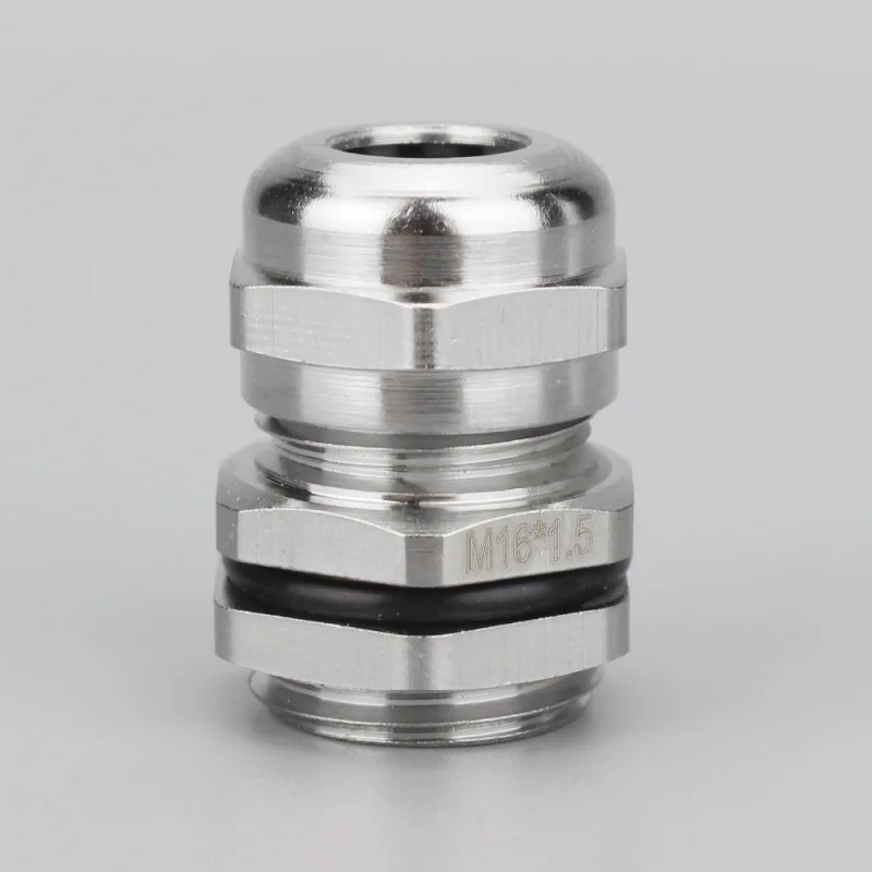
While no exact metric equivalent exists, M16×1.5 represents the closest metric substitute for PG9:
| パラメータ | PG9 | M16×1.5 | Difference |
|---|---|---|---|
| Outer Diameter | 15.2mm | 16.0mm | +0.8mm |
| Thread Pitch | 1.41mm | 1.5mm | +0.09mm |
| Cable Range | 4-8mm | 5-10mm | Larger range |
| Cutout Diameter | 15.2mm | 16.0mm | +0.8mm |
Direct substitution requires panel hole enlargement from 15.2mm to 16.0mm. For existing PG9 holes, reducing bushings or thread adapters enable metric gland installation.
PG9 to NPT Conversion
Converting PG9 to NPT (American tapered pipe thread) is more complex due to fundamentally different thread forms:
- NPT 1/4″ has outer diameter of 13.7mm (smaller than PG9)
- NPT 3/8″ has outer diameter of 17.1mm (larger than PG9)
No direct NPT equivalent exists for PG9. Conversion requires hybrid glands with PG9 external thread and NPT internal bore, or complete panel re-drilling.
Installation Best Practices for PG9 Cable Glands
Proper PG9 installation ensures IP rating achievement and long-term reliability.
Step-by-Step Installation Process
- Panel preparation: Drill or punch 15.2mm diameter hole with smooth, burr-free edges
- Component sequence: Thread lock nut, washer, gland body, and seal onto cable in correct order
- Cable insertion: Push cable through gland until proper length extends for termination
- Seal positioning: Center compression seal around cable with even circumferential contact
- Panel mounting: Thread assembled gland into panel hole from exterior side
- Lock nut tightening: Hand-tighten lock nut from panel interior until finger-tight
- Compression torque: Apply final torque per manufacturer specification (typically 2-5 Nm for PG9)
- Visual verification: Confirm seal compression is visible and no gaps exist
Common Installation Errors
Avoid these frequent mistakes when installing PG9 cable glands:
- Incorrect cable diameter: Using cables outside 4-8mm range prevents proper seal compression
- Missing seal elements: Omitting washers or seal inserts compromises IP rating
- Over-tightening: Excessive torque cracks plastic glands or damages seals
- Panel deformation: Thin panels require backing washers to prevent material crushing
- Cable damage: Sharp panel edges nick cable jackets, creating moisture entry paths
Applications and Industry Usage
PG9 cable glands serve diverse industrial applications where their mid-range cable capacity aligns with common wire sizes.
Control Panel and Switchgear
Electrical control cabinets frequently specify PG9 for:
- PLC input/output modules requiring 4-6mm control wire
- Push-button station connections
- Indicator light wiring
- Relay and contactor control circuits
Sensor and Instrumentation
Industrial sensors commonly use PG9 glands for:
- M12 connector pigtail cables (5-7mm OD)
- Proximity sensor cables with integral connectors
- Temperature sensor RTD and thermocouple wiring
- Pressure transducer signal cables
Machine Tools and Automation
Manufacturing equipment employs PG9 for:
- Servo motor encoder feedback cables
- Limit switch wiring on CNC machines
- Pneumatic valve solenoid connections
- Human-machine interface (HMI) communication cables
HVAC and Building Systems
Building automation specifies PG9 for:
- BACnet and Modbus communication networks
- Variable frequency drive (VFD) control wiring
- Actuator and damper motor cables
- Energy meter pulse output connections
Procurement and Specification Guidelines
When specifying PG9 cable glands for projects, include these key parameters in procurement documents:
Minimum specification requirements:
- Thread type: PG9 per DIN 46320
- Material: Nickel-plated brass, nylon 66, or stainless steel 316
- Cable range: 4-8mm (verify against actual cable OD)
- IP rating: IP65 minimum (or higher as required)
- Seal material: NBR or specified alternative
- Temperature rating: Match application environment
- Quantity and delivery timeline
- Compliance certifications: CE, UL, CSA as applicable
Request material certifications confirming brass composition, plating thickness, and seal compound specifications. For critical applications, require third-party IP rating testing verification.
Maintenance and Lifespan Considerations
Installed PG9 cable glands require minimal maintenance but benefit from periodic inspection:
- Quarterly visual checks in harsh environments (outdoor, chemical exposure)
- Annual inspections in controlled indoor installations
- Lock nut retorquing if vibration loosening is detected
- Seal replacement every 5-7 years or when cracking/hardening appears
- Complete gland replacement if cable modifications are performed
PG9 cable glands are not reusable after removal—compressed seals lose integrity and require complete assembly replacement to restore IP ratings.
Related Products & Resources
Recommended Cable Gland Products
- M Series M40A Outdoor Equipment Stainless Steel Cable Gland – Metric alternative for larger cables
- 産業オートメーション M48 ステンレス鋼ケーブルグランド – Heavy-duty automation applications
- ケーブルグランド M50A 高強度メートルねじグランド – High-strength metric option
- M42A 屋外用メトリックシリーズ防塵ケーブルグランド – Outdoor panel installations
- Stainless Steel Cable Gland IP68 Watertight M33A – Submersible applications
Related Technical Guides
- The Ultimate Cable Gland Size Chart You Must Use Today – Complete PG, metric, and NPT sizing reference
- ケーブルグランド設置ガイド防水シーリングのためのプロフェッショナルな7つのヒント – Installation best practices
- Proximity Sensor Selection Guide: How to Choose the Right Type – Sensor cables requiring PG9 termination
External Authority References
- DIN Standard Organization: DIN 46320 Cable Gland Standards
- Thread Conversion Charts: Metric, PG, and NPT Thread Comparison Guide