


What is a Current Transformers?1-minute understand
A current transformers (CT) is a device used to safely measure alternating current in power systems by stepping a large line current down to a much smaller, manageable value in its secondary winding, while keeping the ratio proportional between primary and secondary currents for accurate calculation of the original current. This reduced current can then be sent to meters, protective relays, data loggers, or SCADA systems, which use it for monitoring, billing, and protecting connected equipment from abnormal operating conditions.
This article decodes the step-down method and the principle behind how current transformers operate by deconstructing it down to fundamental parts.
How Does a Current Transformers Work
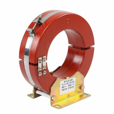
A Low Voltage Residual Leakage current transformer main job is to scale down high alternating current into a lower, safer value that instruments can handle without being exposed directly to dangerous line current. It usually uses a core-and-coil structure with primary and secondary windings to achieve this effect.
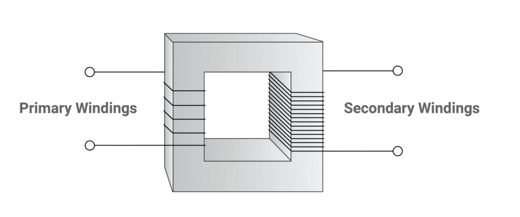
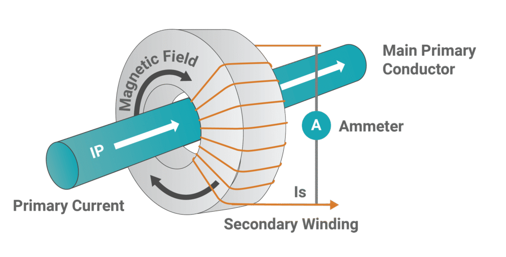
Inside, there is a primary winding and a secondary winding, both made of copper wire, wrapped around a core built from ferromagnetic materials such as silicon steel or iron. The primary winding is placed in series with, or directly around, the current‑carrying conductor, so when current flows through it, a magnetic flux is created in the core. That core channels and concentrates the magnetic flux, which then induces a proportional current in the secondary winding; this induced value is what we call the secondary current.
You can picture this process as two electric fans pointed at each other. When the first fan (the primary) is switched on, it pushes air (like magnetic flux) toward the second fan. The moving air makes the second fan spin, similar to how magnetic flux induces current in the secondary winding. The faster the first fan spins (the larger the primary current), the stronger the airflow, and the faster the second fan turns, just as a higher primary current produces a larger induced secondary current.
How Does Step-Down Method Work
In a current transformer, the step-down effect comes from the fixed relationship between the primary and secondary currents and the number of turns on each winding. The secondary current is directly proportional to the primary current, as described by Ampere’s law and Faraday’s law.
The basic relationship is:
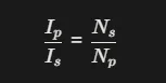
where Ip is primary current, Is is secondary current, Np is the number of primary turns, and Ns is the number of secondary turns. This means the current ratio is the inverse of the turns ratio: if you increase the number of turns on the secondary compared to the primary, the secondary current becomes smaller in proportion.
The turns ratio Np:Ns is called the turns ratio. In a typical current transformer, this ratio is less than 1, so the primary has fewer turns than the secondary. Because of the inverse relationship, a small number of primary turns and a larger number of secondary turns cause the secondary current IsIs to be much lower than the primary current IpIp, which is how the CT steps the current down to a safer, measurable level.
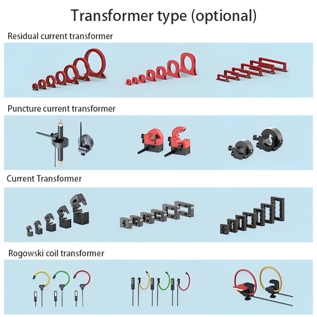
Three Types of Current Transformers
Different types of current transformers were developed to match specific uses. These types are usually grouped by shape: wound Current Transformers, toroidal Current Transformers, and bar Current Transformers.
Wound Current Transformer
A wound current transformer has both primary and secondary windings wrapped on a magnetic core. The primary side is made with multiple turns of wire. Because both Np そして Ns can be chosen freely, the transformation ratio can be adjusted very precisely. This is the most common and standard style of CT.
Toroidal Current Transformer
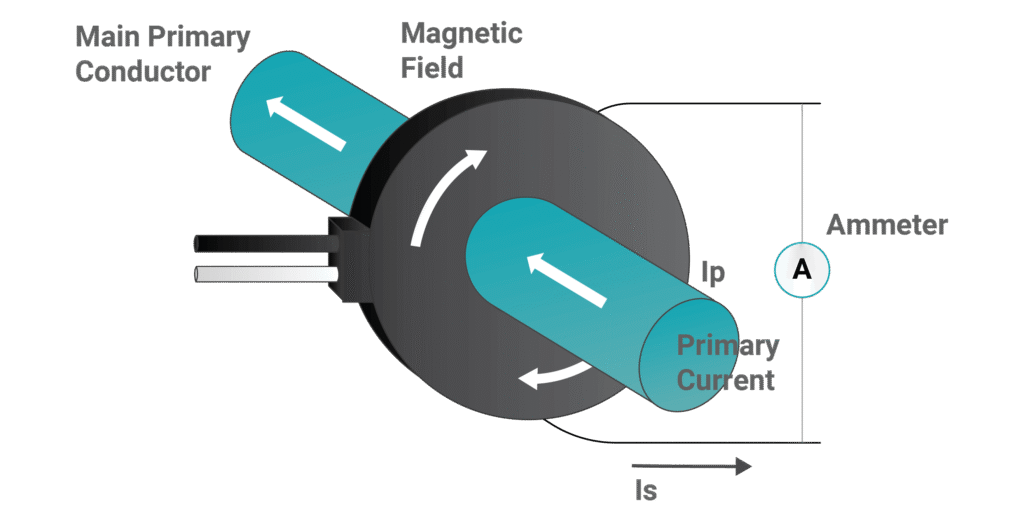
A toroidal current transformer is similar to a wound CT but does not include a dedicated primary winding. Instead, it is built as a ring, and the existing current-carrying conductor is passed through the center. That conductor becomes the primary, so in this case Np=1.
Bar Current Transformer
A bar current transformer operates like a toroidal CT, but the conductor acting as the primary is fixed in place and cannot be removed. This design is especially suitable for measuring very high currents.
Split-Core CTs vs. Solid-Core CTs
In real installations, toroidal CTs are widely used because they do not need a separate primary winding, which makes installation easier. However, installing a standard toroidal CT still requires disconnecting the live conductor so it can be routed through the core, which interrupts normal operation. Split-core Current Transformers were created to avoid this interruption.

A split-core CT has a core made from two or more pieces that can be opened and closed. This lets the CT clamp around an existing live conductor without shutting down the system. That makes it very useful where non-intrusive and quick installation is important. Some split-core CT models, such as those used for revenue-grade energy metering, can still provide high accuracy while offering this flexibility.
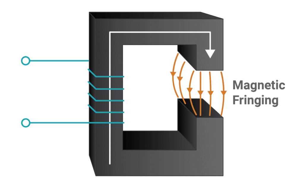
A solid-core Current Transformer, in contrast, has a single, unbroken magnetic core. This design offers better accuracy and long-term stability. In a split-core CT, the hinge and closing mechanism leave a small air gap in the core. The air gap has a different magnetic permeability than the core material, which affects how easily the core can be magnetized. This mismatch creates magnetic fringing, where part of the magnetic field strays from the ideal path. As a result, measurement accuracy is slightly reduced. A solid-core Current Transformers has no air gap, so the magnetic flux stays within the core path, and accuracy is maintained.
Current Transformers Accuracy Classes
Current transformers are grouped into accuracy classes that describe how close their measured current is to the real primary current across a defined range. IEC 61869-2 is the main international standard that defines these accuracy classes for measuring CT.
According to IEC 61869-2, common accuracy classes for Current Transformer are 0.1, 0.2, 0.5, 1, 3, 5, and their “S” variants 0.1S, 0.2S, and 0.5S. These numbers represent the maximum percentage ratio error allowed at specified percentages of rated current; for example, a Class 0.5 CT is allowed up to ±0.5% ratio error at rated current under specified burden conditions.
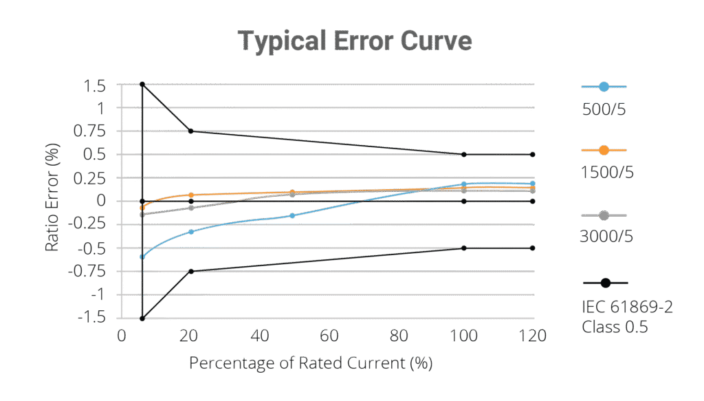
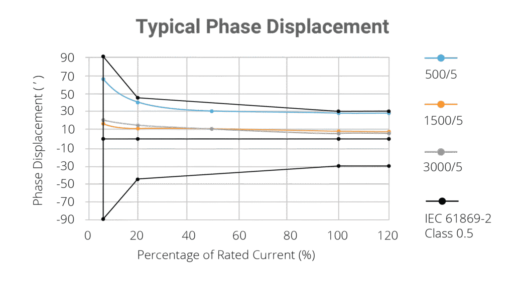
In a typical error curve for an IEC 61869-2 Class 0.5 CT, the horizontal axis shows the primary current as a percentage of its rated value, and the vertical axis shows ratio error in percent. Class 0.5 requires that when the primary current is at 100% of rated current and up to a defined overcurrent (for example up to 120% of rated), the ratio error must stay within ±0.5%. The “S” versions, such as Class 0.5S, tighten the requirements at lower current levels so the CT remains accurate down to a smaller fraction of its rated current, which is important for precise metering at light load.
When a Current Transformers meets IEC 61869-2 accuracy Class 0.5 or better (for example 0.5, 0.5S, 0.2, or 0.2S) over the required current and burden range, it is commonly described as revenue-grade, meaning its performance is suitable for billing and other commercial metering uses where small errors translate directly into money gained or lost. Besides ratio error, CT accuracy is also influenced by phase displacement, which is the phase angle difference between primary and secondary currents. IEC 61869-2 specifies limits for this phase displacement for each class at various percentages of rated current, and typical plots show how the allowed phase angle error varies with load current for a given class, such as Class 0.5.
Real-Life Applications of Current Transformers
Current transformers are used wherever high alternating current needs to be measured or monitored safely, such as in energy metering, industrial automation, and renewable energy systems like solar and wind installations. They let instruments see a low, proportional current or voltage instead of the full line current, making monitoring safer and more practical.
Traditionally, Current Transformers provided standardized secondary currents of 1 A or 5 A, which matched the inputs of most legacy meters and protection devices. With the growth of solar and wind power, CTs with a 333 mV voltage output have become popular because they simplify wiring and interface well with modern electronic meters and data loggers. These CTs include an internal burden resistor that converts current to a small voltage, so the secondary does not need grounding, which improves safety and makes installation easier.
The 333 mV designs are often more cost‑effective and can achieve very good accuracy thanks to carefully designed internal components and winding arrangements. Beyond metering, Current Transformer play a key role in protection: they sense abnormal overcurrent conditions and feed that signal to protective relays, which then trip breakers or contactors to isolate downstream circuits. Protection‑class CTs must withstand very high fault currents, often up to 20 times their rated current, without failing or saturating in a way that prevents relays from operating correctly.
Safe installation is critical. The Current Transformers must be rated for at least the maximum expected primary current, and, for types that require it, the secondary should be grounded as specified to avoid dangerous voltages and ensure proper operation. Technicians also need to consider physical size so the conductor fits through the window or around the bar, as well as the CT’s rated current range. The CT will only meet its specified accuracy when the actual current stays within a defined band, commonly from about 5% up to 120% of its rated current, so choosing the right rating is essential for reliable measurements.
よくあるご質問
What is a current transformer (CT)?
A current transformer is an electrical device that scales high current down to a lower, proportional value so it can be measured safely for monitoring, billing, and equipment protection.
How does a current transformer work?
The CT primary is connected to the high‑current conductor and creates magnetic flux in an iron core, which induces a proportional current in the secondary winding, thus “shrinking” the current by a fixed ratio.
What is the step‑down principle in a CT?
The ratio between primary and secondary current is inversely related to the number of turns in the primary and secondary windings, so using more turns on the secondary than on the primary steps a large current down to a smaller one.
What are the common structural types of current transformers?
By form factor, the main types are wound current transformers, toroidal current transformers, and bar‑type current transformers.
What is special about a wound current transformer?
It has separate primary and secondary windings on the core, with multiple turns on the primary, so both turn counts can be adjusted to set an accurate transformation ratio; this is the most common standard design.
What is a toroidal current transformer?
A toroidal CT is ring‑shaped and has no dedicated primary winding; the existing current‑carrying conductor passes through the core and acts as the primary, so the primary has one turn.
How does a bar current transformer differ from a toroidal CT?
It works on the same principle as a toroidal CT, but the primary conductor (often a busbar) is built in and fixed, making it well suited for very high current applications.
What is a split‑core current transformer?
A split‑core CT has a core made of two or more parts that can be opened and closed, allowing the CT to be clamped around an energized conductor without disconnecting it.
What are the advantages of a split‑core CT?
It can be installed on existing live conductors without shutting down the system, which makes it flexible and convenient for retrofits and non‑intrusive installations, including many metering applications.
Which is more accurate: split‑core or solid‑core CTs?
Solid‑core CTs use a single, continuous core with no air gaps, so they typically offer higher accuracy and better stability than split‑core CTs, whose joints create small gaps and magnetic leakage.
What is a CT accuracy class?
Accuracy class defines how much measurement error a CT is allowed to have; IEC 61869‑2 specifies common classes such as 0.1, 0.2, 0.5, 1, 3, 5 and the “S” classes 0.1S, 0.2S, and 0.5S, where a lower number means higher accuracy.
What is the difference between Class 0.5 and Class 0.5S?
Both have similar error limits at rated current, but Class 0.5S has tighter error and phase‑displacement limits at low currents, making it better for accurate metering under light‑load conditions.
What is a revenue‑grade current transformer?
A revenue‑grade CT meets IEC 61869‑2 accuracy Class 0.5 or better (for example 0.5S, 0.2, or 0.2S) over the specified operating range, so it is suitable for utility billing and other financial metering uses.
What is phase displacement in a CT?
Phase displacement is the phase‑angle difference between the primary and secondary currents; standards place limits on this because it directly affects accurate measurement of active and reactive power.
Where are current transformers commonly used?
They are widely used for high‑current measurement, energy and power monitoring, industrial automation, and in renewable energy systems such as solar PV and wind power, as well as in power‑system protection.
Why did traditional CTs use 1 A or 5 A secondary outputs?
Secondary currents of 1 A and 5 A became standard so that meters and protective relays could be designed around common input ratings, simplifying design, selection, and interchangeability.