Motor Thermal Damage Curve vs Relay Trip Curve
Six points, two lines, three conditions. Plot the thermal damage curve against the relay trip curve and know exactly what the overlaps mean.
Read More
A contactor cross reference table tells you which devices do the same job. It does not tell you which device will bolt into the same holes, accept the same overload relay, and pass the same certification review. Those are different questions, and confusing them is how a “direct replacement” turns into a panel rebuild at 2 a.m.
This guide gives the mapping across the three families most commonly encountered in export and replacement work, then sets out the three preconditions that decide whether a functional equivalent is actually a drop-in. It assumes you have already decoded the existing model number; if not, start with how to read a contactor model number.
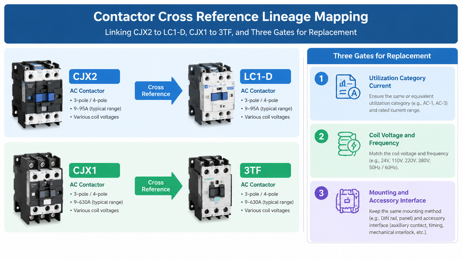
Most Chinese IEC contactor families are derived from a specific European original, which is why cross-references exist at all:
Once you know which lineage you are dealing with, the mapping becomes mechanical. Before ordering, verify the current rating at the actual utilization category, the coil voltage and frequency, and the mounting and accessory interface. All three, every time.
The equivalents below are the commonly published functional pairings. They describe devices that perform the same switching duty; they are not manufacturer endorsements, and the current ratings do not align perfectly at every step.
| Duty (approx. AC-3, 400 V) | CJX2 family | LC1-D / LC1-F | CJX1 family | 3TB / 3TF |
|---|---|---|---|---|
| 9 A | CJX2-0910 | LC1-D09 | CJX1-09 | 3TB40 |
| 12 A | CJX2-1210 | LC1-D12 | CJX1-12 | 3TB41 |
| 16–18 A | CJX2-1810 | LC1-D18 | CJX1-16 | 3TB42 |
| 22–25 A | CJX2-2510 | LC1-D25 | CJX1-22 | 3TB43 |
| 32 A | CJX2-3210 | LC1-D32 | CJX1-32 | 3TB44 |
| 40–45 A | CJX2-4011 | LC1-D40 | CJX1-45 | 3TF46 |
| 50–63 A | CJX2-5011 / 6511 | LC1-D50 / D65 | CJX1-63 | 3TF47 |
| 75–80 A | CJX2-8011 | LC1-D80 | CJX1-75 | 3TF48 |
| 85–95 A | CJX2-9511 | LC1-D95 | CJX1-85 | 3TF49 |
| 110–115 A | CJX2-D115 | LC1-D115 | CJX1-110 | 3TF50 |
| 170 A | CJX2-D170 | LC1-D170 | CJX1-170 | 3TF52 |
| 225 A and above | CJX2-F225 upward | LC1-F225 upward | CJX1-205 / 250 | 3TF53 / 3TF54 |
Read the table as a starting point, not an answer. Note the mismatches: 16 A against 18 A, 40 A against 45 A, 110 A against 115 A. Those gaps exist because the two lineages rate their frames differently at 400 V and at 690 V, and because AC-3 ratings change with the voltage you are actually switching. A device that is an exact equivalent at 400 V may be a step down at 690 V.
Every row above is AC-3, the standard motor-switching category. If the existing device is switching a resistive heater, a capacitor bank, or a motor that is plugged and reversed, the comparison has to be made in AC-1, AC-6b or AC-4 instead, and the numbers will not line up the way the table suggests.
Practically: find the utilization category and voltage on the original device or in its datasheet, then compare ratings in that same category. Comparing an AC-3 rating on one side against an AC-1 rating on the other is the most common way a “same amps” replacement ends up undersized. The category definitions are in AC-1 to AC-4 utilization categories.
Coil codes are not portable between brands. The Schneider code M7 means 220 V 50 Hz; the equivalent CJX2 coil letter code is M for 220 V, but the frequency is a separate digit and a dual-frequency coil is a different part. A device with the right amps and the wrong coil is not a replacement, it is a return.
Check three things on the original: measured coil voltage at the terminals, frequency, and whether the coil is AC or DC. Where the panel is fed from a 24 V DC control bus, an AC coil will not work at all regardless of what the cross-reference says.
This is where functional equivalence and physical fit part company. A contactor carries three interfaces beyond its own footprint:
The overload relay is the one that hurts. An LRD relay does not mount on a Siemens 3RT frame, and a 3RU2 does not mount on an LC1-D. If the existing starter uses a direct-mounted thermal relay, a contactor swap becomes a starter rebuild unless the new family has its own matching relay. The device-level differences are set out in contactor vs circuit breaker for the protection side, and in thermal overload relay vs MPCB for the protection architecture question.
| Item | Interchangeable? | Why |
|---|---|---|
| Contactor main frame | Functionally, yes — within the rating checks above | Same switching duty, different physical design |
| Direct-mount overload relay | No | Mechanical interface is family-specific; needs its own matching relay |
| Auxiliary contact blocks | No | Clip geometry and contact spacing differ between families |
| Mechanical interlock kit | No | Designed for one frame pair only; a reversing pair must be matched |
| Surge suppressor | No | Coil terminal spacing and voltage class differ; see surge suppressor selection |
| Certification evidence | No | UL file numbers and CE declarations belong to the device, not the rating |
Certification deserves its own line because it is invisible until an inspector asks. A functional equivalent rated for the same current may be IEC-certified only, while the original carried a UL listing that the panel’s approval depends on. For North American panels this is decisive; the UL versus IEC split is discussed in NEMA Class 20 vs IEC Class 10 for the overload element, and applies equally to the contactor.
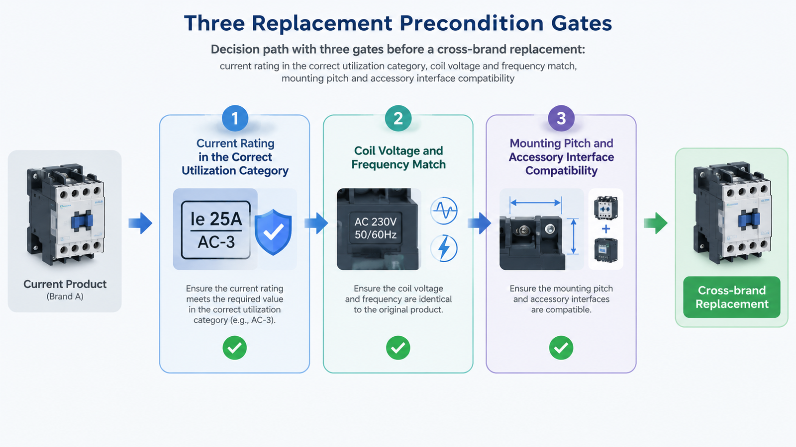
Steps 5 and 6 are the ones that decide whether the job takes an hour or a weekend. Both are visible from a photograph and a datasheet if you check before ordering.
Cross-reference tables are useful precisely because the families share a lineage, and dangerous for the same reason: the ratings line up closely enough to look interchangeable while the mounting, accessories and certification do not. Match the family, verify the current in the right utilization category, write the coil voltage and frequency down explicitly, and treat the overload relay and auxiliaries as new parts rather than carry-over parts.
For the compact range that covers most 9–95 A replacements, the LC1-D series contactor range is the direct LC1-D equivalent; the AC contactor category lists the larger D and F frames for the 115 A and above replacements.
Functionally yes for standard AC-3 motor switching, and the current ratings map closely. It is not a drop-in for mounting, auxiliary blocks or direct-mount overload relays, which are family-specific.
Usually through the CJX1 family, which follows the 3TB/3TF frame logic, rather than through CJX2. Verify the current rating at your voltage and check that a matching overload relay exists in the chosen family.
Because each lineage rates its frames at different voltages and categories. A 40 A device in one family may be listed as 45 A in another at 400 V, and the relationship changes again at 690 V. Compare in the same utilization category.
Generally no. Direct-mount relays have family-specific mechanical and electrical interfaces, so a contactor swap usually requires the matching relay from the new family.
The full original model number, coil voltage and frequency, utilization category and voltage, auxiliary contact configuration, and a photograph showing the mounting and any direct-mounted relay.
Not automatically. Certification belongs to the device, not the rating, so a functional equivalent may be IEC-only where the original carried a UL listing. Confirm before specifying for an approved panel.