Motor Thermal Damage Curve vs Relay Trip Curve
Six points, two lines, three conditions. Plot the thermal damage curve against the relay trip curve and know exactly what the overlaps mean.
Read More
The auxiliary contacts on a contactor are usually the last thing specified and the first thing that causes a panel modification. A starter needs one NO contact to seal itself in, one NC contact to interlock with something else, and one more contact to tell the PLC the motor is actually running — that is three, and a bare contactor often ships with one. The result is an add-on block ordered late, a side-mount that does not fit next to the neighbour, or a control circuit that quietly shares a contact between two functions.
This guide is about sizing and configuring auxiliary contacts rather than what they are: how many you need, which type each function demands, where the contacts physically come from, how timing heads and interlocks change the count, and how to specify the rating properly. If you need the underlying difference between an auxiliary contact and a main power contact, that is covered in auxiliary versus main contacts.
An auxiliary contact performs exactly one signalling job. Count the jobs, and that is your minimum contact count — then add one spare NO and one spare NC, because panel modifications never remove functions.
| 機能 | Contact type needed | Typical count |
|---|---|---|
| Seal-in (self-holding) circuit | ノー | 1 |
| Electrical interlock against another contactor | NC | 1 per interlocked pair |
| Run feedback to PLC or DCS | NO (run) and often NC (stopped) | 1–2 |
| Indicator lamp (local or panel door) | ノー | 1 per lamp |
| Sequence / step logic in a relay panel | NO or NC depending on logic | 1–2 |
| Safety monitoring (mirror / force-guided) | NC mirror contact | 1 |
| Alarm or fault annunciation | NC | 0–1 |
| Spare for future modification | 1 NO + 1 NC | 2 |
For a plain direct-on-line starter with a PLC watching, that adds up to three or four. For a reversing pair it is five to six, because each contactor needs its own interlock contact and the pair shares the external signalling.
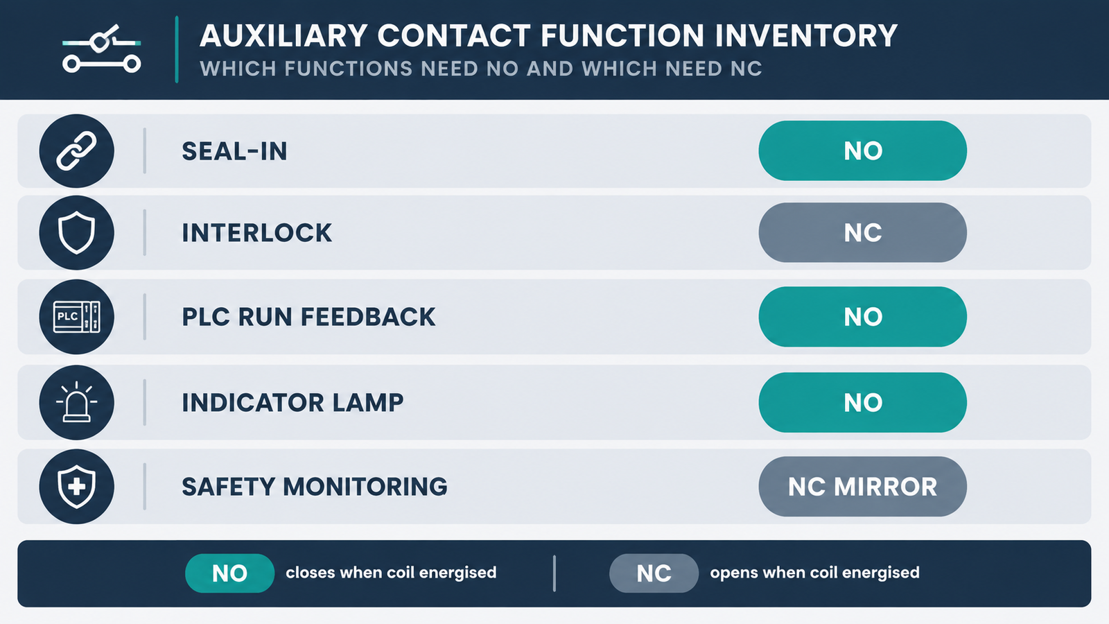
The choice is not a preference — it is defined by what the circuit must do when the contactor is at rest.
The common error is wiring a seal-in circuit through an NC contact because the terminal was physically convenient. The starter then drops out the instant the start button is released, which reads as a “faulty contactor” when it is only a wrong terminal.
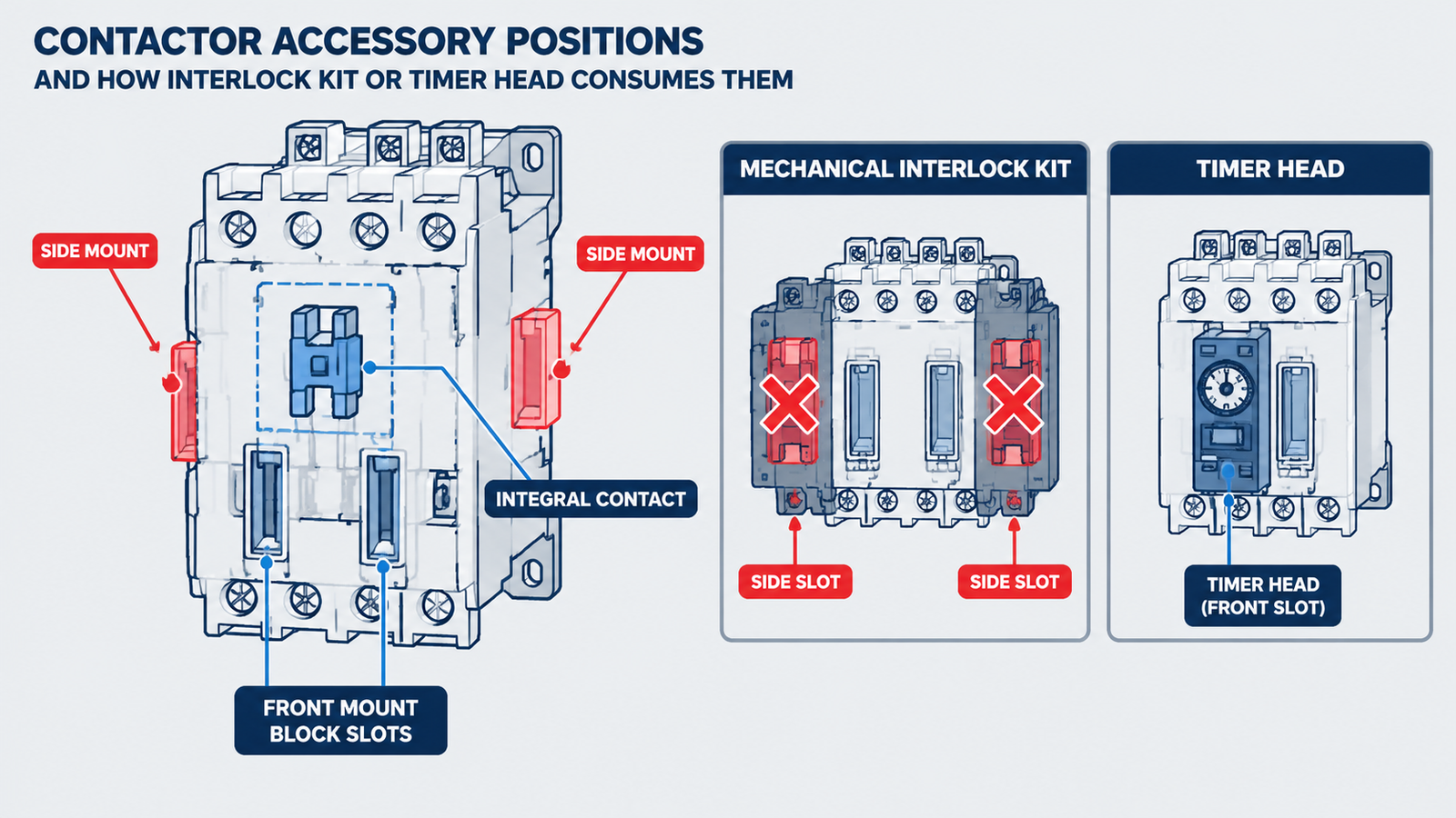
Auxiliary contacts are not unlimited. Each frame has a defined accessory budget, and the budget is consumed differently depending on where the blocks mount.
| Source | Typical capacity | Notes |
|---|---|---|
| Integral (moulded into the frame) | 1 NO, or 1 NO + 1 NC | Fixed; cannot be changed or removed. Common on small frames. |
| Front-mount block | 1–2 blocks, each 1–4 contacts | Fits over the coil area; the standard first add-on |
| Side-mount block | 1 per side, 1–2 contacts each | Left and right are separate positions; a neighbour contactor may block access |
| Timer head (pneumatic or electronic) | 1 timing contact set | Replaces a front block position rather than adding to it |
| Mechanical interlock kit | Occupies the facing sides | Consumes the side-mount positions on both contactors |
Two practical consequences follow. First, a reversing pair with a mechanical interlock kit has no side-mount positions left — all additional contacts must come from front blocks or be integral, which is why reversing assemblies are usually ordered with the contacts pre-configured. Second, a timer head takes a front position, so “add a timer” and “add two front aux blocks” are competing requirements, not additive ones.
When the frame is nearly full, the answer is often a larger frame rather than more blocks: contact count is part of the frame selection, and a 9 A frame with four add-on blocks can cost more and occupy more panel depth than a 25 A frame with the contacts built in.
Some functions are not “on when the contactor is on” but “on some seconds after” or “on for a short while after it drops out”. Those need a timing contact, which is a block with a built-in delay rather than a plain auxiliary.
| タイプ | 機能 | Accuracy | 代表的な使用例 |
|---|---|---|---|
| Pneumatic (air-dashpot) timer head | On-delay or off-delay, set by a screw | Rough — affected by dust, temperature and mounting position | Legacy star-delta starters |
| Electronic timer head | On-delay / off-delay, DIP or dial set | Tight and repeatable | New panels, sequence control, pump changeover |
| Star-delta changeover block | Fixed transition window | Set by the block’s design | Dedicated star-delta starters |
For new work, electronic heads are the default: they hold their setting across temperature and mounting orientation, whereas a pneumatic head that was accurate on the bench can drift once it is mounted at an angle in a hot enclosure. In a star-delta starter the timing contact is not optional — it defines the transition window, and too short a window produces a current transient larger than the original direct-on-line start.
Interlocking is the most common reason to add an NC contact, and it is also the most commonly misunderstood.
Electrical interlock is a normally-closed auxiliary contact from contactor A wired into the coil circuit of contactor B, and vice versa. It costs one NC contact per contactor and works by removing the competing coil’s supply whenever the first contactor is picked up.
Mechanical interlock is a physical linkage that prevents both armatures from being closed at once, independent of any control wiring. It is required on reversing and changeover pairs, and it consumes the facing side positions on both devices.
You need both, and they are not substitutes: the electrical interlock acts first and is defeated by a welded auxiliary contact, while the mechanical interlock survives control-circuit faults but cannot stop a contactor whose main contacts have already welded. The interaction between the two — and the dead time a reversing pair needs — is set out in reversing contactor arrangements.
| Configuration | NO needed | NC needed | Total | Notes |
|---|---|---|---|---|
| DOL starter, local push buttons only | 1 (seal-in) | 0 | 1 | Integral contact often enough |
| DOL starter with PLC monitoring | 2 (seal-in, run) | 1 (stopped feedback) | 3 | Most common configuration in new panels |
| DOL with run and trip lamps | 2 | 1 | 3 | Trip lamp usually driven from the overload’s 97/98 instead |
| Reversing pair (forward + reverse) | 2 (one per direction) | 2 (electrical interlock, one per contactor) | 4 | Plus a mechanical interlock kit; side positions consumed |
| Star-delta starter | 2–3 | 2 (interlock between star and delta) | 4–5 | Timing head occupies a front position |
| Safety-related stop with monitoring | 1 | 1 mirror contact | 2 | Mirror contact is a distinct feature, not a standard NC |
An auxiliary contact’s rating is not a single number. The relevant figure is the utilisation category, normally AC-15 for AC control circuits and DC-13 for DC electromagnet loads, expressed as a rated operational current at a stated voltage — for example 10 A at 240 V AC under AC-15. That is a different rating from the 10 A thermal current (Ith) printed next to it, and the thermal figure alone tells you nothing about switching capability.
Two specification traps follow. A contact rated for AC-15 duty is not automatically suitable for a DC-13 load at the same current, because DC arcs do not self-extinguish at a zero crossing; the DC-13 current at 220 V DC is typically a fraction of the AC-15 current at 220 V AC. And on the opposite end, when an auxiliary contact feeds a PLC input or a low-level signal, the relevant limit is the minimum switching capacity — often around 17 V and 5 mA. Below that, the contact film does not break down and the signal becomes intermittent. For those circuits, gold-plated or gold-flashed contacts are the correct choice, not a bigger contactor.
| Mistake | Consequence | Correction |
|---|---|---|
| Ordering the contactor without counting functions | Late add-on block, extra freight, panel rework | Count functions at specification, add one spare NO and NC |
| Assuming side-mount positions will be free on a reversing pair | Interlock kit blocks both sides; nothing fits | Order the reversing assembly with contacts pre-configured |
| Using a timer head where a plain front block was planned | Contact count drops by one when the timer is fitted | Budget the timer position separately |
| Sharing one NO contact between seal-in and PLC feedback | Feedback reads true even when the circuit has failed | One contact, one function |
| Using a standard NC contact where a mirror contact is required | Safety function cannot be validated; certification issue | Specify force-guided / mirror contacts explicitly |
| Reading the thermal current as the switching rating | Contact erosion or welding in service | Rate on AC-15 / DC-13 at the actual circuit voltage |
Wiring practice for the blocks themselves — including how the seal-in and interlock loops are physically routed — is covered in how to wire a contactor. When the signalling is being handled by a dedicated control relay rather than the contactor’s own contacts, the trade-off between the two devices is set out in contactor versus control relay.
A small frame usually ships with one NO contact, either integral or as a fitted front block. Larger frames often include 1 NO + 1 NC, and DIN-rail modular contactors may have none by design. Always confirm from the frame’s accessory list rather than assuming.
13/14 is a normally-open contact and 21/22 is normally-closed. In IEC numbering the units digit defines the function — 1 and 2 for NC, 3 and 4 for NO — and the tens digit defines which contact it is, so 21/22 is the NC pair of contact number 2.
No. Each frame has a defined accessory budget and mounting positions. Some small frames have fixed integral contacts with no add-on capability, and side positions may be blocked by a neighbouring device or by a mechanical interlock kit.
Yes, if the feedback is meant to prove the contactor actually closed. Sharing the seal-in contact with the PLC input means the input reads true whenever the control circuit is energised, including when the main contacts have failed to close.
A normally-closed auxiliary contact mechanically guaranteed never to be closed at the same time as the main poles. It is used in safety circuits to prove the main contacts are open. It is a specific product feature — a standard NC contact does not provide that guarantee.
Often not well. DC-13 ratings are much lower than AC-15 ratings at the same voltage, and very low-current signals fall below the contact’s minimum switching capacity. For signal-level DC, specify gold-plated contacts or use a solid-state interface.
Auxiliary contacts are a budget, not a feature list. Count the functions the circuit actually performs, assign NO or NC by what must be true at rest, then check the frame’s accessory positions — remembering that a timer head and a mechanical interlock kit consume positions rather than adding to them. Add one spare of each type, rate the contacts on AC-15 and DC-13 rather than thermal current, and specify mirror contacts explicitly wherever a safety function depends on them. For frames with configurable front and side auxiliary blocks, the CJX2-F225 contactor page lists the available contact configurations, and the AC contactor category covers the full range.